
21.4.5 PWM Duty Cycle
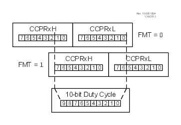
The PWM duty cycle is specified by writing a 10-bit value to the CCPRx register. The alignment of the 10-bit value is determined by the FMT bit (see Figure 21-5). The CCPRx register can be written to at any time. However, the duty cycle value is not latched onto the 10-bit buffer until after a match between T2PR and T2TMR.
The equations below are used to calculate the PWM pulse width and the PWM duty cycle ratio.
The CCPRx register is used to double buffer the PWM duty cycle. This double buffering is essential for glitchless PWM operation.
The 8-bit timer T2TMR register is concatenated with either the 2-bit internal system clock (FOSC), or two bits of the prescaler, to create the 10-bit time base. The system clock is used if the Timer2 prescaler is set to 1:1.
When the 10-bit time base matches the CCPRx register, then the CCPx pin is cleared (see Figure 21-4).