
4.2.1.2 LP, XT, HS Modes
The LP, XT and HS modes support the use of quartz crystal resonators or ceramic resonators connected to OSC1 and OSC2 (Figure 4-3). The three modes select a low, medium or high gain setting of the internal inverter-amplifier to support various resonator types and speed.
LP Oscillator mode selects the lowest gain setting of the internal inverter-amplifier. LP mode current consumption is the least of the three modes. This mode is designed to drive only 32.768 kHz tuning-fork type crystals (watch crystals).
XT Oscillator mode selects the intermediate gain setting of the internal inverter-amplifier. XT mode current consumption is the medium of the three modes. This mode is best suited to drive resonators with a medium drive level specification (between 100 kHz - 4 MHz).
HS Oscillator mode selects the highest gain setting of the internal inverter-amplifier. HS mode current consumption is the highest of the three modes. This mode is best suited for resonators that require a high drive setting (above 4 MHz).
Figure 4-3 and Figure 4-4 show typical circuits for quartz crystal and ceramic resonators, respectively.

- A series resistor (RS) may be required for quartz crystals with low drive level.
- The value of RF varies with the Oscillator mode selected (typically between 2 MΩ to 10 MΩ).
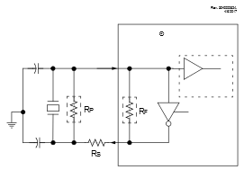
- A series resistor (RS) may be required for ceramic resonators with low drive level.
- The value of RF varies with the Oscillator mode selected (typically between 2 MΩ to 10 MΩ).
- An additional parallel feedback resistor (RP) may be required for proper ceramic resonator operation.