
6.6.1.2 Zigbee Application Demo: Light Control and Monitoring using Alexa Echo Plus
WBZ351 Curiosity Board
Devices (Device): | PIC32CX5109BZ31048(MCU) on WBZ351 Module |
Peripherals (Used, On-Board): | RGB LED | User Button| UART-USB Converter|
Introduction
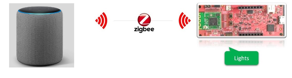
This page describes the demo steps for WBZ351 Curiosity board Extended Light control and Monitoring using Amazon Echo Plus (Zigbee gateway).
An overview of the demo is shown below.
GitHub Repository
The firmware, .hex, and accompanying readme.md file
for the application can be found in the GitHub repository – ext_light
Hardware Requirement
| S. No. | Tool | Quantity |
|---|---|---|
| 1 | WBZ351 Curiosity Boards | 1 |
| 2 | Micro USB cable | 1 |
| 3 | Amazon Echo Plus (Built-in Zigbee smart home hub) | 1 |
| 4 | Smart Phone with Alexa app installed | 1 |
| 5 | Personal Computer | 1 |
Hardware Modification
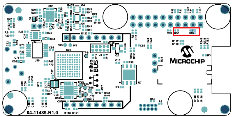
A simple hardware modification is needed to run this demo. WBZ351 Curiosity boards has on-board RGB LED on PB0, PB3, PB5 pins. But, these pins are multiplexed with CVD Touch functionality. Hence the connection to R and B LED's are disconnected by default on the board. Mount 0 ohm resistor or make the solder connection on R92 and R95 resistor position as shown below.
SDK Setup
Refer to Getting Started with Software Development from Related Links.
Software Requirement
To install Tera Term tool, refer to the Tera Term web page in Reference Documentation from Related Links.
Programming the precompiled hex file or Application Example
Using MPLAB® X IPE:
-
Import and program the precompiled hex file:
<Discover Path>\wireless_apps_pic32cxbz3_wbz35\apps\zigbee\ext_light\hex - For detailed steps, refer to Programming a Device in MPLAB® IPE in Reference Documentation from Related Links.Note: Ensure to choose the correct Device and Tool information.
Using MPLAB® X IDE:
-
Perform the following the steps mentioned in Running a Precompiled Example. For more information, refer to Running a Precompiled Application Example from Related Links.
-
Open and program the Application Example
ext_light.xlocated in<Discover Path>\wireless_apps_pic32cxbz3_wbz35\apps\zigbee\ext_light\firmware - For more details on how to find the Discover path, refer to Download Application Example from Discover in Running a Precompiled Application Example from Related Links.
Demo Description
The demo applications demonstrates the Zigbee protocol functionality of PIC32CXBZ/WBZ family of devices and modules. It consists of a ZigBee 3.0 Coordinator and Router implemented as shown below:
| Application | Zigbee Logical Device Type | Functionality |
|---|---|---|
| Amazon Echo Plus | Coordinator | Device capable of controlling and monitoring other devices. |
| Extended Lights | Router | Is a lighting device that can be switched on/off , brightness & color of the light can be adjusted via the color commands. |
Zigbee device commissioning:
-
The Zigbee router i.e. Extended Lights can be commissioned and brought to the existing Zigbee network formed by Zigbee gateway i.e. Amazon Echo Plus or can create new Zigbee Distributed network (if there is no nearby network).
Zigbee light control:
-
Extended light RGB LED can be controlled from Zigbee Gateway of the same network.
-
When the light status is changed the light change report will be sent to Zigbee gateway through Zigbee communication.
Demo Steps:
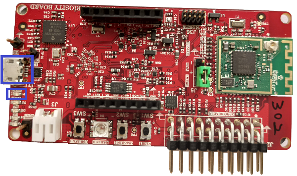
- Supply power to WBZ351 Curiosity Board consisting of Extended light
application by connecting a USB cable. Power Supply (PS) Green LED will turn on
when connected to PC.
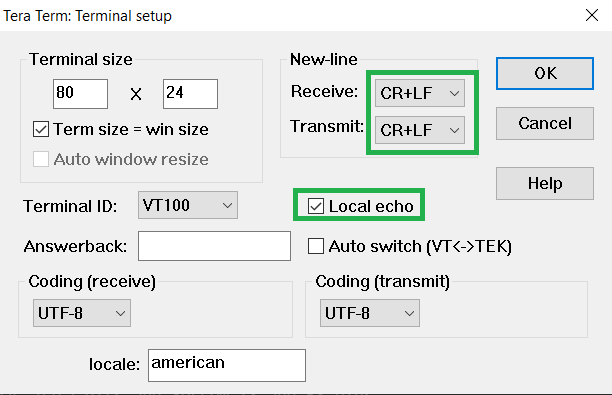
- The application activity is shown as “Console Log” through on board UART-USB converter:
-
Open Terminal (Example: Tera Term) with the setup as shown below to look for these logs.
-
On the PC side virtual COM port connection that corresponds to the board shall have following settings:
BAUD RATE: 115200 (as configured in SERCOM configuration)
PARITY: None
DATA BITS: 8
STOP BITS: 1
FLOW CONTROL: None
Commissioning (Router - Extended Light)
Light can be added to Alexa's Zigbee network by voice commands or by using Alexa mobile app.-
Voice Commands: Open Alexa to discover the Light device. Say “Discover my devices”. or
-
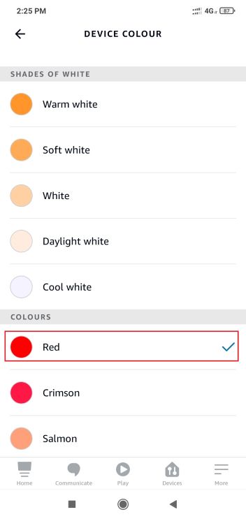
Alexa App:
- Launch Alexa app, from the menu, select the Add Device.
- Select the type of smart home device “Light” and select “Other”.
- Initiate Discover Devices.
- Input command :
resetToFN on light device.The Light will be discovered and
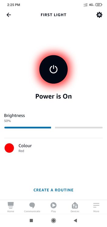
shown as light in Alexa app as shown below.
Figure 6-16. . 
-
Either through voice commands like “Alexa, Turn on my first light”, “Alexa, Change color of my first light to “GREEN””, “Alexa, increase the brightness of my first light” or from Alexa app the RGB LED can be controlled through Zigbee network.
 ---->
----> 
Other Functionalities:
-
On board button actions:
-
When the on board “User Button (SW3)” is pressed for more than 10sec, it can delete all the networking information and will bring the device to factory default state. This functionality is available in both combined interface and light devices.
-
-
Persistent Data Storage (PDS): The RGB light status (On/Off) and brightness values are stored in non-volatile memory called PDS. So, power off/on of extended light, these values persist and RGB LED will reflect accordingly. This PDS storage is tied to Zigbee network.
-
The light On/Off status, color and light brightness is being stored in non-volatile memory in this case. So, power off/on, the LED will be updated with light on/off and brightness values retrieved from previous transaction.
-
Creating Application Device Types From Scratch Using MCC
- Create a new harmony project. For more details, see Creating a New MCC Harmony Project from Related Links.
- Option 1: Import component
configuration: This step helps users’ setup the basic components and configuration
required to develop this application. The imported file is of format
.mc4and is located in the path<Discover Path>\wireless_apps_pic32cxbz3_wbz35\apps\zigbee\ext_light\firmware\ext_light.X.Note: Import and export functionality of the Harmony component configuration will help users to start from a known working setup of the MCC configuration. - Option 2: Follow the remaining steps.
- Click + symbol on the Extended
Color Light Device Type component from “Device Resources”.
- Accept dependencies or
satisfiers, select Yes to all.


- Configure Extended Color
Light as shown:

- Accept dependencies or
satisfiers, select Yes to all.
- Add UART components needed for console logs and commands. Right click on the yellow
triangle to add satisfiers as shown below. Verify the UART SERCOM configuration as
in Zigbee Console Commands.


- Add TCC2 to the project graph.

- Add TCC0 to the project graph and
verify the configuration options.


- Add TC2 and TC3 to the project graph
and verify the configuration options.


- Add EIC to the project graph and
verify the configuration options.


- Add Bootloader Services to the
project graph.

- Verify if the Project Graph window
has all the expected MCC configurations.

- Configure the following pins in the Pin Configuration.


- Add the
bootloader_timer.X.production.hex fileas a loadable in the project properties. The hex file can be found in
folder.<Harmony Content Path>\wireless_apps_pic32cxbz3_wbz35\apps\zigbee\ext_light\firmware\ext_light.X