
3.1 Adding and Configuring MPLAB Harmony Components
To add and configure MPLAB Harmony components using the MCC, follow these steps:
- In the MCC window, from the Plugins drop-down list, select the required
Configuration Window.
Figure 3-6. MPLAB Code Configurator – Plugins List 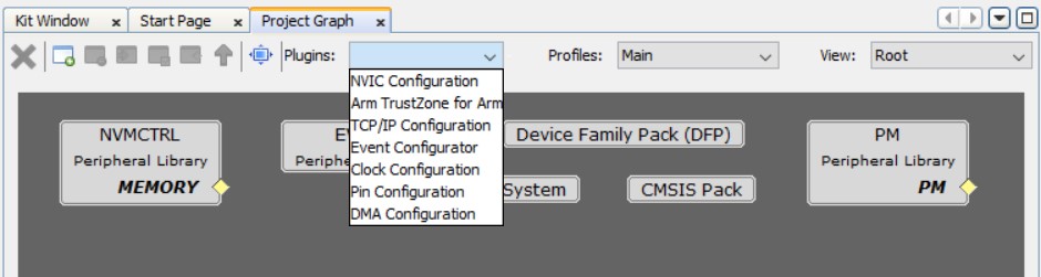
- Select Clock Configuration to
open the Clock Easy View window and verify that the Main Clock is set to 48 MHz.
Figure 3-7. MPLAB Code Configurator - GCLK Generator 0 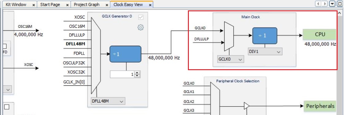
- Click Project Graph and then
select the System module. In the Configuration Options Properties Page,
configure it as follows to enable the SysTick timer for the Secure and Non-Secure
time delay.
Figure 3-8. MPLAB Code Configurator – SysTick Configuration 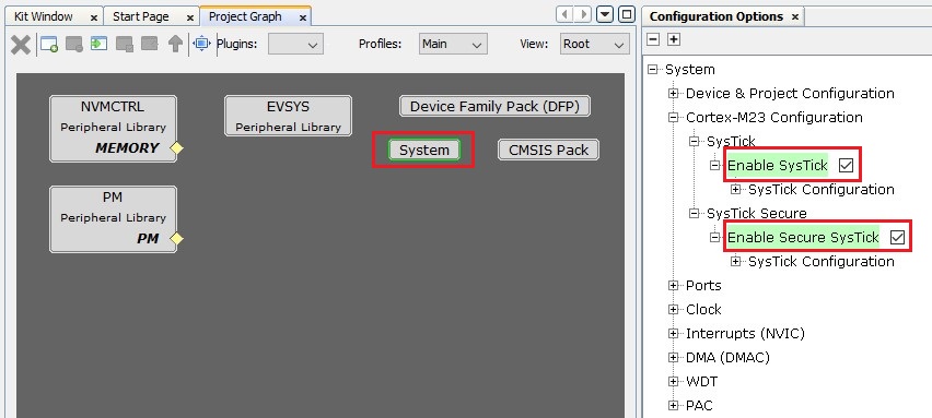
- Select NVMCTRL Peripheral Library
MEMORY and in the Configuration Options Properties Page, configure it as
follows to enable the Tamper Erase feature.
Figure 3-9. MPLAB Code Configurator – NVMCTRL Configuration 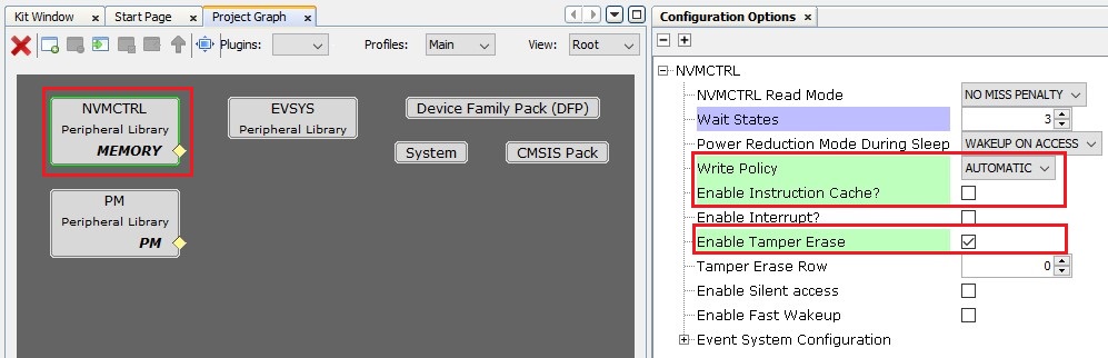
- Click Resource Management
(MCC) and under Device Resources, click and expand Harmony >
Peripherals > EIC. Click EIC and observe that the EIC Peripheral
Library block is added in the Project Graph Window.
Figure 3-10. MPLAB Code Configurator - Selection of EIC Peripheral 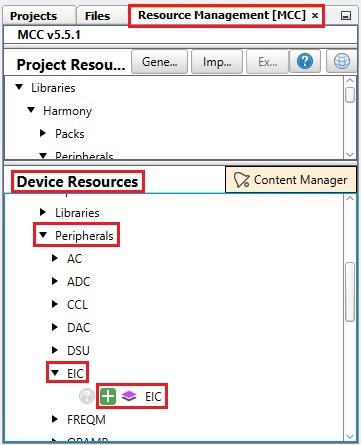
- Select EIC Peripheral Library
and in the right Configuration Options Property Page configure it as follows to use
the EIC channel 2 (SW1) as tamper input.
Figure 3-11. MPLAB Code Configurator - EIC Configuration 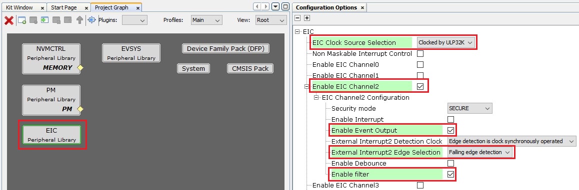
- Under Device Resources, click and expand Harmony > Peripherals > RTC. Click RTC and observe that the RTC Peripheral Library block is added in the Project Graph Window.
- Select RTC Peripheral Library and in the Configurations Options Property
page configure it as follows to generate a compare interrupt every 30 seconds and
enable the tamper interrupt and events.
Figure 3-12. MPLAB Code Configurator - RTC Configuration Note: The Compare Value is set as 0x7800. This value generates an RTC compare interrupt every 30 seconds.- RTC clock = 1024 Hz
- RTC Prescaler = 1
- Required Interrupt rate = 30s
Therefore, Compare Value = 30 x 1024 = 30,720 (i.e., 0x7800).
- Under Device Resources:
- Click and expand Harmony > Peripherals > SERCOM. Click SERCOM3 and observe that the SERCOM3 block is added in the Project Graph Window.
- Click and expand Harmony > Peripherals > Tools. Click Secure
STDIO and observe that the Secure STDIO block is added in the
Project Graph Window.
Figure 3-13. MPLAB Code Configurator – SERCOM and Secure STDIO Selection 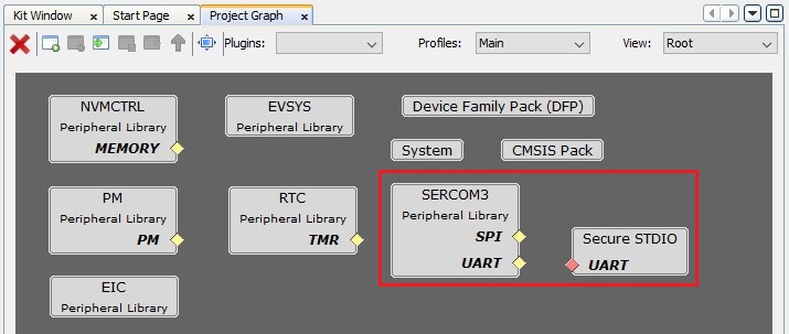
- Connect the SERCOM3 and Secure STDIO
block by dragging the UART Yellow Diamond to the Red Diamond in the Secure STDIO
block.
Figure 3-14. MPLAB Code Configurator – SERCOM and Secure STDIO Selection 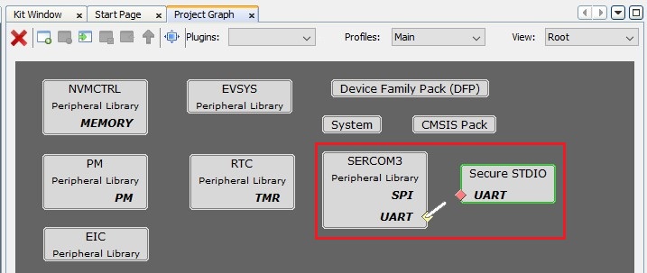
- In the left pane, select SERCOM3
Peripheral Library. In the Configuration Options property page, configure it
as follows to print the data on the Serial Console at 115200 baud rate.
Figure 3-15. MPLAB Code Configurator – SERCOM3 Configuration 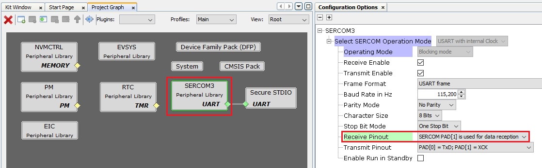
- From the Plugins drop-down
list, select Event Configurator. Add the Event Generator and Event User for
tamper input as shown in the following figure.
Figure 3-16. MPLAB Code Configurator – Event Configuration - From the Plugins drop-down
list select Pin Configuration and then click Pin Settings tab. Change
the order to Ports. Make the pin configurations according to the application
as indicated below.
Figure 3-17. Pin Settings Window - Pin Configuration Note:- PB08, PB09: SERCOM3 TX and RX pins
- PA15: LED
- PA23: SWITCH
For additional information, refer to the PIC32CM LS00 Curiosity Nano+ Touch Evaluation Kit User Guide (DS70005567).
Figure 3-18. PIC32CM LS00 Curiosity Nano+ Touch Board Pinout - Select System in the Project
graph. In the Configuration Options property page, configure it as follows to set
the Memory Configuration for the Non-Secure Callable Size to zero.
Figure 3-19. MPLAB Code Configurator – Memory Configuration