
5.1 Introduction
The Device Programming window (also known as the programming dialog) gives you the most low-level control of the debugging and programming tools. With it, you can program the device's different memories, fuses, and lock bits, erase memories, and write user signatures. It can also adjust a few starter kit properties, such as voltage and clock generators.
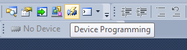
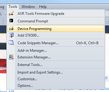
The programming dialog is accessible from a button on the standard toolbar or the menu Tools → Device Programming.
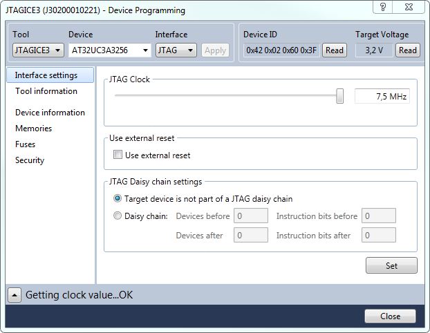
The programming dialog contains the following options and tabs:
Top Status Bar
Tool
You can choose which tool you want to use from this drop-down menu. Only tools connected to the machine are listed. Also, if a tool is used in a debug session, it will not be listed. Several tools of the same type can be connected at the same time. The serial number will be shown below the tool name in the list to identify them.
When a tool is selected, the name (and serial number) shows in the title bar of the Device Programming dialog.
Device
As soon as a tool is selected, the device list will show all devices supported by that tool. There are two ways to choose a device:
-
Select from the list
Clicking on the arrow will reveal the list of supported devices. Click to select.
-
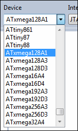
Select by typing. In this example, we will select the ATxmega128A3:
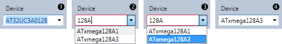
- Double click in the text field to select the text already present.
- Start typing some part of the device's name (in this example, 128A). The list updates while you type, showing all devices containing what is typed.
- Press the Arrow Down keyboard button to move the selection into the list. Use the up and down keys to navigate. Press ENTER to make a selection.
- The ATxmega128A3 is now selected.
Note: A red border around the device selector indicates that the text entered is not a valid device name. Continue typing until the device name is complete, or select from the list.
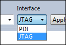
Interface
When a tool and a device are selected, the interface list will show the available interfaces. Only interfaces available on both the tool and the device will appear in this menu.
Select the interface to use to program the AVR.
Apply Button
When the tool, device, and interface are selected, press the Apply button to make the selections take effect and set up a connection to the tool. The list on the left side of the window will be updated with the relevant pages for the selected tool.
If a different tool, device, or interface is selected, press the Apply button again to make the new selections take effect.
Device ID
Press the Read button to read the signature bytes from the device. The device's unique tag will appear in this field and can be used for tool compatibility checking and to obtain help either from customer support or from the AVR Freaks® people.
Target Voltage
All tools are capable of measuring the target's operating voltage. Press the refresh button to make a new measurement.
A warning message will appear if the measured voltage is outside the operating range for the selected device, and the target voltage box will turn red.