
1.1.12.1.3 Configuring The Library
The AT25DF driver library should be configured through the MHC. The following figures show the MHC configuration window for the AT25DF driver and brief description.
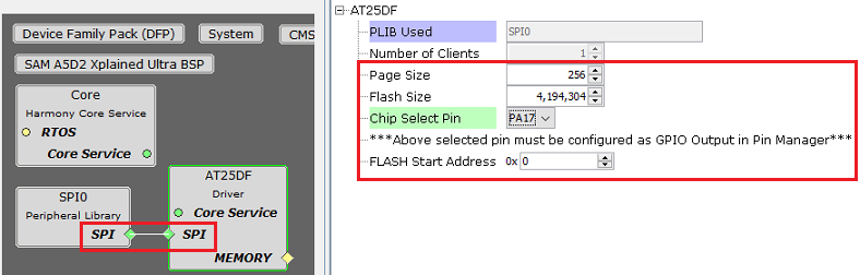
AT25DF Driver with SPI peripheral connected
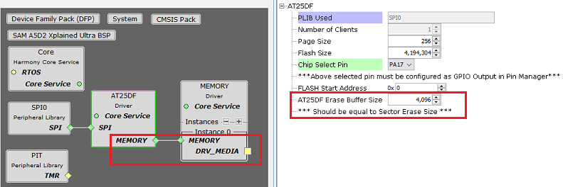
AT25DF Driver with connection to Memory Driver
Configuration Options
PLIB Used:
- Specifies the Peripheral library connected
Number Of Clients:
Indicates maximum number of clients
Always set to one as it supports only a single client
Page Size:
- Size of one page of FLASH memory (in bytes)
Flash Size:
- Total Size of the FLASH memory (in bytes)
Chip Select Pin:
FLASH chip select pin (active low)
This pin must be configured as GPIO output in "Pin Settings" configuration
AT25DF Flash Start Address:
Specifies the flash memory start address to be used for Transfer operations
The start address will be populated in the device geometry table DRV_AT25DF_GEOMETRY
AT25DF Erase Buffer Size:
This option appears only when the AT25DF driver is connected to the Memory driver for block operations
Specifies the size for erase buffer used by Memory driver
The size of the buffer should be equal to erase sector size as the memory driver will call DRV_AT25DF_SectorErase