
3.2 External INT0, INT1 Pin Configuration
To enable external INT0, INT1 pin interrupt function enable, EICRA (external interrupt control register A) register should be configured to select the sensing mode – falling edge, rising edge, logic change, or low level, and enable INT0, INT1 interrupt request bits of the EIMSK (external interrupt mask register).
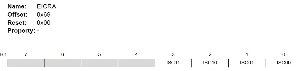
Bits 3:2 – ISC1n: Interrupt Sense Control 1 [n = 1:0]
| Value | Description |
|---|---|
| 00 | The low level of INT1 generates an interrupt request |
| 01 | Any logical change on INT1 generates an interrupt request |
| 10 | The falling edge of INT1 generates an interrupt request |
| 11 | The rising edge of INT1 generates an interrupt request |
Bits 1:0 – ISC0n: Interrupt Sense Control 0 [n = 1:0]
| Value | Description |
|---|---|
| 00 | The low level of INT0 generates an interrupt request |
| 01 | Any logical change on INT0 generates an interrupt request |
| 10 | The falling edge of INT0 generates an interrupt request |
| 11 | The rising edge of INT0 generates an interrupt request |
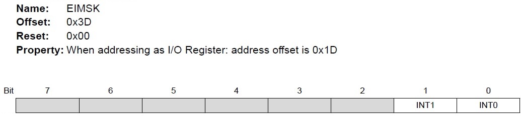
Bit 1 – INT1: External Interrupt Request 1 Enable.
Bit 0 – INT0: External Interrupt Request 0 Enable.