
3.4 Pin Change Interrupt Configuration
For enabling a PCINT pin change interrupt function, first the pin direction input mode must be configured; secondly, it needs to set the PCINTn bit to “1” in the PCMSK register, and finally it needs to set the corresponding PCIE0~3 bit in PCICR register.
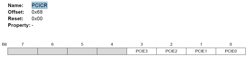
Bit 3 – PCIE3: Pin Change Interrupt Enable 3
When the PCIE3 bit is set, any change on any enabled PCINT[27:24] pin will cause an interrupt. PCINT[27:24] pins are enabled individually by the PCMSK3 Register.
Bit 2 – PCIE2: Pin Change Interrupt Enable 2
When the PCIE2 bit is set, any change on any enabled PCINT[23:16] pin will cause an interrupt. PCINT[23:16] pins are enabled individually by the PCMSK2 Register.
Bit 1 – PCIE1: Pin Change Interrupt Enable 1
When the PCIE1 bit is set, any change on any enabled PCINT[15:8] pin will cause an interrupt. PCINT[15:8] pins are enabled individually by the PCMSK1 Register.
Bit 0 – PCIE0: Pin Change Interrupt Enable 0
When the PCIE0 bit is set, any change on any enabled PCINT[7:0] pin will cause an interrupt.
PCINT[7:0] pins are enabled individually by the PCMSK0 Register.