37.3.7 Bus Time-Out
The SMBus protocol requires a bus watchdog to prevent a stalled device from holding the bus indefinitely. The I2C Bus Time-out Clock Source Selection (I2CxBTOC) register provides several clock sources that can be used as the time-out time base. The I2C Bus Time-out (I2CxBTO) register is used to determine the actual bus time-out time period, as well as how the module responds to a time-out.
- SCL =
0(regardless of whether or not the bus is Active) - SCL =
1and SDA =0while the bus is Active
If either condition is true, an internal time-out counter increments and continues to
increment as long as the condition stays true or until the time-out period has expired.
If these conditions change (e.g., SCL = 1), the internal time-out
counter is reset by module hardware.
The Bus Time-out Clock Source Selection (BTOC) bits select the time-out clock source. If an oscillator is selected as the time-out clock source, such as the LFINTOSC, the time-out clock base period is determined by the oscillator frequency. If a timer is selected as the time-out clock source, the timer can be configured to produce a variety of time periods.
1),
the time-out period determined by the TOTIME bits is multiplied by 32. If TOBY32 is
clear (TOBY32 = 0), the time-out period determined by the TOTIME bits
is used as the time-out period. For example, if a value of ‘35’ is written into the
TOTIME bits and LFINTOSC is selected as the time-out clock source with TOBY32 bit set,
the time-out period is approximately 35 ms as demonstrated in 35 ms BTO Period Configuration.35 ms BTO Period Configuration
void Init_BTO_35(void)        // Selections produce a 35 ms BTO period
{
  I2C1BTOC = 0x06;               // LFINTOSC as BTO clock source
  I2C1BTObits.TOREC = 1;         // Reset I2C interface, set BTOIF
  I2C1BTObits.TOBY32 = 1;        // BTO time = TOTIME * TBTOCLK * 32
  I2C1BTObits.TOTIME = 35;     // TOTIME = TBTOCLK * 35
                                 // = 1 ms * 35 = 35 ms

}
1), the
I2C module is reset and module hardware sets the Bus Time-out Interrupt
Flag (BTOIF). If the Bus Time-out Interrupt Enable (BTOIE) is also set, an interrupt will be generated. If a bus time-out occurs
and TOREC is clear (TOREC = 0), the BTOIF bit is set, but the module is
not reset.1) and a bus time-out event occurs
(regardless of the state of the Client Mode Active (SMA)
bit), the module is immediately reset, the SMA and Client Clock Stretching (CSTR) bits are cleared, and the Bus Time-out Interrupt Flag (BTOIF) bit is set.0) and a bus time-out event occurs
(regardless of the state of the Client Mode Active (SMA)
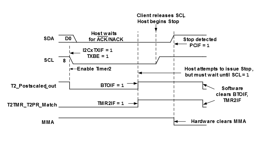
bit), the BTOIF bit is set, but the user software must reset the module.1) and the bus time-out event occurs
while the host is active (Host Mode Active (MMA) =
1), the Host Data Ready (MDR)
bit is cleared, the module will immediately attempt to transmit a Stop condition, and
the BTOIF bit is set. Stop condition generation may be delayed if a client
device is stretching the clock but will resume once the clock is released or if the
client holding the bus also has a time-out event occur. The MMA bit is only cleared
after the Stop condition has been generated.0), and the bus time-out
event occurs while the host is active (Host Mode Active (MMA) = 1), the MDR bit is cleared and the BTOIF bit is set, but user software must initiate the Stop
condition by setting the P bit.The figure below shows an example of a Bus Time-out event when the module is operating in Host mode.

