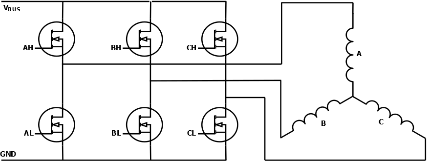
The power stage is comprised of an inverter, which consists of three half-bridges that can either tie each phase to the supply voltage or ground. The switching element is typically a MOSFET, for low-voltage applications, or an IGBT, for high-voltage applications.

The AH, BH and CH represent the high-side command signals from the microcontroller, while AL, BL and CL represent the low-side signals.
In addition to the power transistors, MOSFET/IGBT drivers are used to ensure good rise and fall times and provide the gate voltage needed for the high-side and low-side transistors.
A combinational logic circuit is used to avoid shoot-through by adding dead time between the high-side and low-side command signals.
This dead time ensures the MOSFETs or IGBTs on the same branch are completely turned off and do not conduct current at the same time.