
1.9 Ethernet
The SAM E54 Curiosity Ultra development kit has a modular Ethernet PHY system that enables different PHYs to be plugged into the board. This interface is setup to use a Reduced Media-Independent Interface (RMII) and a SPI bus interface with GPIO. The following figure illustrates the Ethernet PHY header configuration.
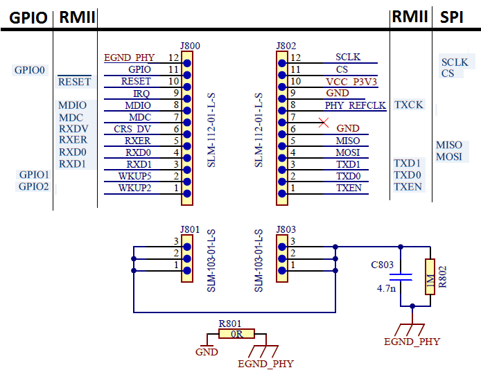
The following table provides the Ethernet PHY interface pinout descriptions.
| Pin Number | Name | Description |
|---|---|---|
| 1 | GPIO | General purpose I/O |
| 2 | GPIO | General purpose I/O |
| 3 | RXD1 | Receive Data 1 |
| 4 | RXD0 | Receive Data 0 |
| 5 | RXER | Receive Error |
| 6 | RXDV | Receive Data Valid |
| 7 | MDC | - |
| 8 | MDIO | - |
| 9 | IRQ | Interrupt request line |
| 10 | RESET | Reset control to the Ethernet PHY |
| 11 | GPIO | General purpose I/O |
| 12 | EGND | Shield Ground |
| 13 (1) | TXEN | Transmit Enable |
| 14 (2) | TXD0 | Transmit Data |
| 15 (3) | TDX1 | Transmit Data |
| 16 (4) | MOSI | Host Out Client In line of serial peripheral interface |
| 17 (5) | MISO | Host In Client Out line of serial peripheral interface |
| 18 (6) | GND | Ground |
| 19 (7) | NC | No Connect |
| 20 (8) | REFCLK (in) | Reference Clock input (50 MHz) |
| 21 (9) | GND | GND |
| 22 (10) | +3.3v VDD | +3.3V VDD |
| 23 (11) | CS | Chip Select for serial peripheral interface |
| 24 (12) | SCK | Clock for serial peripheral interface |
| 25 -30 | EGND | Shield Ground |