
1.7 Xplained Pro Standard Extension Header
All Xplained Ultra and Curiosity Ultra Kits have many dual-row, 20-pin, and 100 mil extension headers. Xplained Ultra and Curiosity Ultra MCU boards have male headers, while Xplained Ultra extensions have their female counterparts as shown in the following figure.
Note: All pins are not always connected.
The extension headers can be used to connect a variety of Xplained Pro extensions to Xplained Ultra and Curiosity Ultra MCU boards, or to access the pins of the target MCU on Xplained Ultra MCU or Curiosity Ultra boards directly.
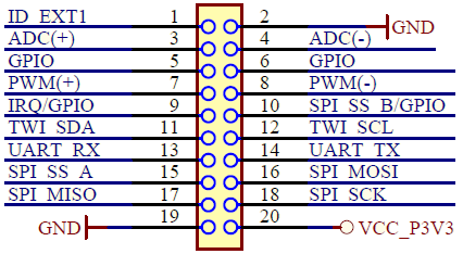
All connected pins follow the defined pinout description as shown in the following table.
| Pin number | Name | Description |
|---|---|---|
| 1 | ID | Communication line to the ID chip on an extension board |
| 2 | GND | Ground |
| 3 | ADC(+) | Analog-to-Digital Converter (ADC), alternatively positive part of differential ADC |
| 4 | ADC(-) | Analog-to-Digital Converter (ADC), alternatively negative part of differential ADC |
| 5 | GPIO1 | General purpose I/O |
| 6 | GPIO2 | General purpose I/O |
| 7 | PWM(+) | Pulse-Width Modulation (PWM), alternatively positive part of differential PWM |
| 8 | PWM(-) | Pulse-Width Modulation (PWM), alternatively negative part of differential PWM |
| 9 | IRQ/INT/GPIO | Interrupt request line and general purpose I/O |
| 10 | SPI SS B/GPIO | SPI Client Select or general purpose I/O |
| 11 | I2C SDA | Data line for I2C interface. Always implemented, bus type |
| 12 | I2C SCL | Clock line for I2C interface. Always implemented, bus type |
| 13 | UART RX | Receiver line of target device UART |
| 14 | UART TX | Transmitter line of target device UART |
| 15 | SPI SS A/GPIO | SPI Client Select or general purpose I/O |
| 16 | SPI MOSI | Host Out Client In line of serial peripheral interface. Always implemented, bus type. |
| 17 | SPI MISO | Host In Client Out line of serial peripheral interface. Always implemented, bus type. |
| 18 | SPI SCK | Clock for serial peripheral interface. Always implemented, bus type. |
| 19 | GND | Ground |
| 20 | VCC | Power for extension boards (3.3V) |