7.5 UART Debug Interface
The ATWILC3000A provides Universal Asynchronous Receiver/Transmitter (UART) interfaces for serial communication in both IEEE 802.11 and Bluetooth subsystems.
-
The Bluetooth subsystem has one 4-pin UART interface (BT UART), which can be used for control and data transfer.
-
The IEEE 802.11 subsystem has one 2-pin UART interface (Wi-Fi UART), which can be used for debugging.
The UART interfaces are compatible with the RS-232 standard, where the ATWILC3000A operates as a Data Terminal Equipment (DTE) type device. The 2-pin UART uses receive and transmit pins (RXD and TXD). The 4-pin UART uses two pins for data (TXD and RXD) and two pins for flow control/handshaking: Request-to-Send (RTS) and Clear-to-Send (CTS).
- Baud rate: 115200
- Data: 8-bit
- Parity: None
- Stop bit: 1-bit
- Flow control: None
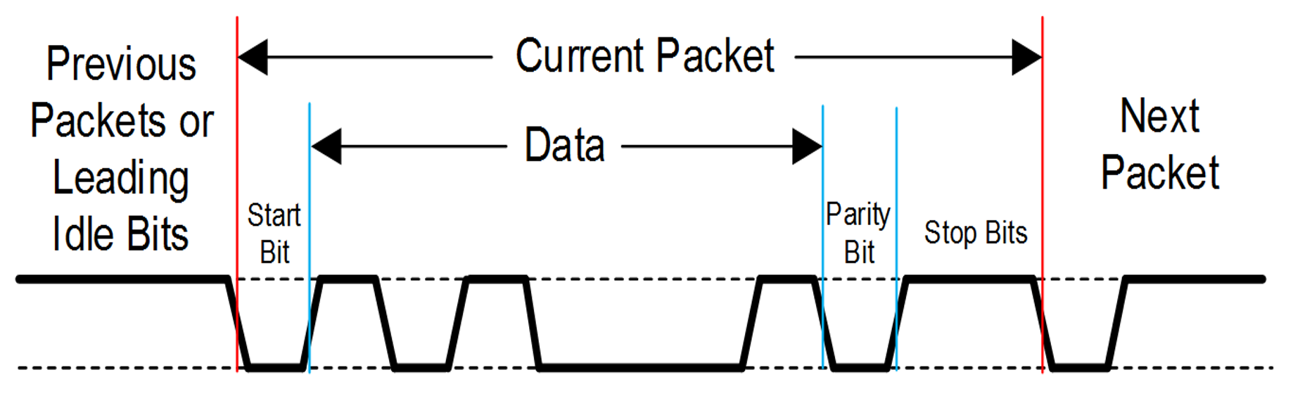
An example of UART receiving or transmitting a single packet is shown in following figure. This example shows 7-bit data (0x45), odd parity and two Stop bits.