2.2.1.1 Start-up Configurator
The Harmony QSpin provides end users with the ability to configure the motor control software modules as per their project requirements.
Start-up Configurator
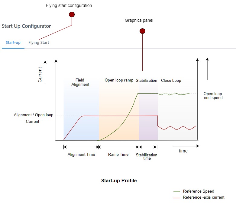
The sensorless position estimation techniques based on back-EMF require a minimum value of back EMF to estimate the electrical position of the rotor. The open-loop start-up procedure drives the PMSM until its speed reaches the minimum value where the back EMF values are large enough to estimate the rotor position.
In the open-loop start-up procedure, the speed loop is de-activated. The currents are controlled directly in the dq reference frame by using assumed rotor position angles for transformations. The complete start-up procedure can be divided into the following phases:
- Initial Field Alignment / Detection. In this phase, the PMSM rotor is locked to a predefined position by maintaining a fixed rotor angle. The d-axis or q-axis current is gradually ramped up to a specified value to prevent overcurrent conditions. In some cases, Initial Position Detection (IPD) is employed to determine the rotor's initial position before starting control. IPD helps ensure accurate field orientation and smooth startup, particularly in sensorless systems, by injecting high-frequency signals or using inductive measurements to estimate the rotor position without requiring motion.
- Open-loop Ramp. In this phase, the rotor position is constantly incremented based on user-defined ramp time to achieve the minimum required speed for the BEMF observer. The minimum ramp time and speed depend on PMSM drive electrical and mechanical parameters. This stage is the most critical step. Any mistuning of reference speed and acceleration can lead to start-up failure.
- Stabilization. In this phase, the PMSM is allowed to rotate at a constant open-loop speed. This step ensures a smooth transition to closed-loop mode.
Graphical User Interface

Rotor Position Alignment / Detection
Follow the steps below to configure the rotor position alignment parameters:
- Click on the Start-up tab rotor position alignment parameters.
- Select the alignment option - Q-Axis alignment, D-axis alignment, or Initial Position Detection.
- If either Q-Axis alignment or D-axis alignment is selected, configure the following parameters:
| Fields | Description |
|---|---|
| Field Alignment/ Detection | Enable alignment |
| Select algorithm | Select Q-Axis alignment or D-axis alignment |
| Alignment current | Set alignment current in Amperes. |
| Alignment time | Set alignment time in seconds. |
If Initial Position Detection is selected, configure the following parameters:
| Fields | Description |
|---|---|
| Field Alignment/ Detection | Enable alignment / detection |
| Select algorithm | Initial Position Detection |
| Pulse Amplitude (in volts) | Set injection pulse amplitude in Volts |
| Pulse Duration (in seconds) | Set injection pulse duty in seconds |
| Pulse Period (in seconds) | Set injection pulse period in Seconds |
Open Loop Start-up
Follow the steps below to configure the open loop start-up parameters:
- Click on the Start-up tab rotor position alignment parameters.
- Configure the following parameters:
| Fields | Description |
|---|---|
| Open loop speed ramp | Enable or Disable open loop start-up |
| Open loop end-speed (RPM) | Open loop start-up end speed in RPM |
| Ramp time (s) | Open loop ramp time in seconds |
| Stabilization time (s) | Open loop stabilization time in seconds |
Flying Start
Follow the steps below to configure the flying start parameters:
- Click on the Flying Startup tab rotor position alignment parameters.
- Configure the following parameters:
| Fields | Description |
|---|---|
| Flying Start | Enable or disable flying start |
| Passive Braking time (s) | Passive braking time in seconds |
| Fade-out burst period | Fade-out burst period in seconds |
| Detection Time | Flying start detection time in seconds |
| Minimum speed (RPM) | Minimum RPM to enable flying start |
| Advanced Configuration | Enable advanced configuration |
| Regenerative Braking | Enable Regenerative Braking |
| Peak braking current (A) | Regenerative braking current |
| Braking ramp time (s) | Brake ramp time in seconds |
Kindly contact Microchip Local Sales for more details.
