2.2.1.6 Position Measurement and Diagnosis
Accurate rotor position measurement is essential in Field-Oriented Control (FOC) to ensure precise control of motor torque and speed. This process involves determining the rotor's position relative to the stator, which is crucial for the effective implementation of the FOC algorithm.
The Position Measurement and Diagnosis GUI allows users to select and configure a wide range of sensored and sensorless methods for position measurement as listed below:
- Classical Microchip Sensorless Algorithm
- Reduced Order Luenberger Observer Algorithm
- Sliding Mode Observer Algorithm
- ZSMT Hybrid Algorithm
- Encoder (without index) Algorithm
Refer to Rotor position measurement principles for more details.
Graphical User Interface
Setting-up Classical Microchip Sensorless Algorithm
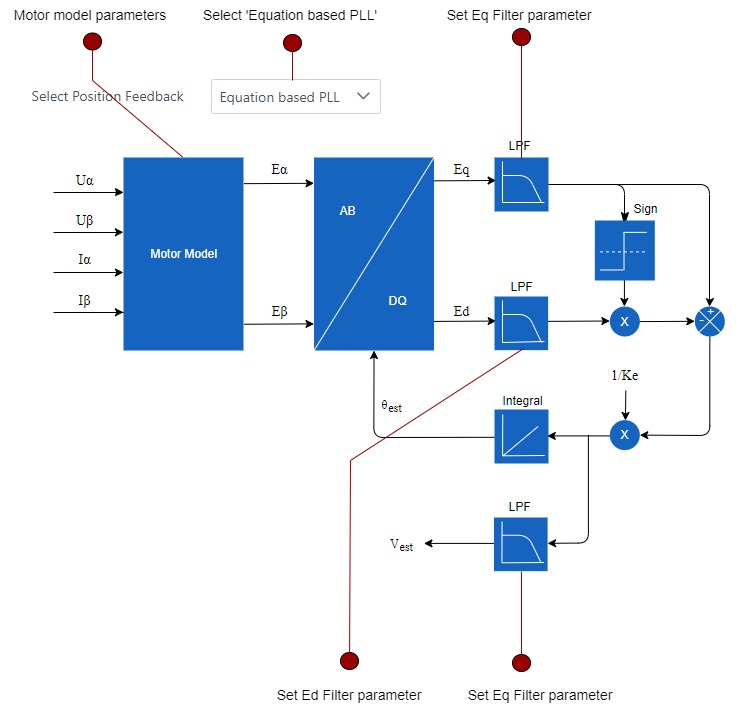
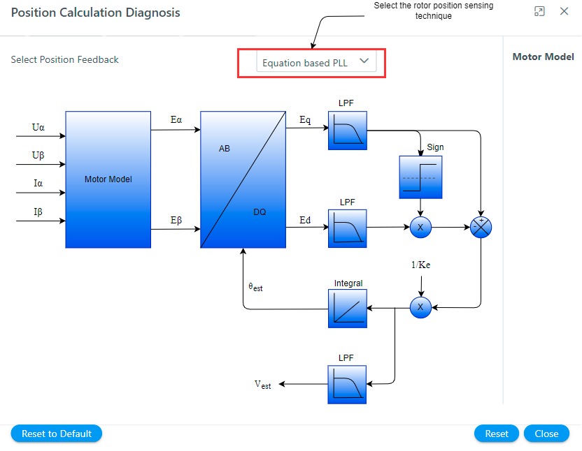
The Classical Microchip Sensorless Algorithm estimates back EMF using straightforward equations and applies a simple Phase-Locked Loop (PLL) to derive rotor position and speed. Its primary advantages are ease of implementation and simplicity, making it well-suited for applications requiring minimal computational effort.
For more details on Classical Microchip Sensorless Algorithm, refer to our application note AN2520.
Follow the following steps to configure Classical Microchip Sensorless Algorithm for rotor position sensing:
- Select Equation based PLL from the 'Select Position Feedback' drop-down menu.
2. View / configure the following parameters:
Motor Model
- Click on the Motor Model block to view motor parameters used in the PMSM model.
- View the following fields in the configuration panel:
| Fields | Description |
|---|---|
| Line-neutral resistance (ohms) | View line to neutral resistance in ohms |
| Line-neutral direct-axis inductance Ld (Henry) | View Line-neutral quadrature-axis inductance Ld (Henry) |
| Line-neutral quadrature-axis inductance Lq (Henry) | View Line-neutral quadrature-axis inductance Lq (Henry) |
| Pole pairs | View pole pairs |
- If the values are 0, go to Motor GUI to select or configure motor parameters.
Ed Filter Parameter
- Click on the Ed LPF block to configure the Ed filter parameter.
- Set the following fields in the configuration panel:
| Fields | Description |
|---|---|
| Filter Parameter | Set the first order Euler filter parameter of the Ed signal. The filter parameter is defined as, with being the sampling time and the filter time constant. |
Eq Filter Parameter
- Click on the Eq LPF block to configure the Eq filter parameter.
- Set the following fields in the configuration panel:
| Fields | Description |
|---|---|
| Filter Parameter | Set the first order Euler filter parameter of the Eq signal. The filter parameter is defined as, with being the sampling time and the filter time constant. |
Speed Filter Parameter
- Click on the Speed LPF block to configure the Speed filter parameter.
- Set the following fields in the configuration panel:
| Fields | Description |
|---|---|
| Filter Parameter | Set the first order Euler filter parameter of the speed signal. The filter parameter is defined as, with being the sampling time and the filter time constant. |
Setting-up Reduced Order Luenberger Observer based position sensing
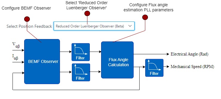
The Reduced Order Luenberger Observer (ROLO) uses a linear observer model to estimate the back EMF, which is then used to calculate rotor position and speed. The key advantage of this approach is its ease of tuning, making it simpler to adjust for different motor parameters.
For more details on the Reduced Order Luenberger Observer, refer to our application note AN2590.
Follow the steps below to configure the Reduced Order Luenberger Observer algorithm:
- Select Reduced Order Luenberger Observer from the 'Select Position Feedback' drop-down menu.
2. View / configure the following parameters:
BEMF Observer
- Click on the BEMF Observer block to configure the observer pole location.
- Set the following fields in the configuration panel:
| Fields | Description |
|---|---|
| Pole location | Pole location of the reduced order Luenberger observer |
Filter Parameter
- Click on the LPF block to configure the () filter parameter.
- Note: This module is currently disabled and reserved for future use
Filter Parameter
- Click on the LPF block to configure the () filter parameter.
- Note: This module is currently disabled and reserved for future use
Flux Angle Calculation
- Click on the Flux Angle Calculation block to configure the PLL used to determine the flux angle from BEMF signals
- Set the following fields in the configuration panel:
| Fields | Description |
|---|---|
| Cut-off Frequency | Set the cut-off frequency of the SRF PLL used for angle and speed estimation |
Speed Filter Parameter
- Click on the Speed LPF block to configure the speed filter parameter.
- Note: This module is currently disabled and reserved for future use
Setting-up Sliding Mode Observer based position sensing
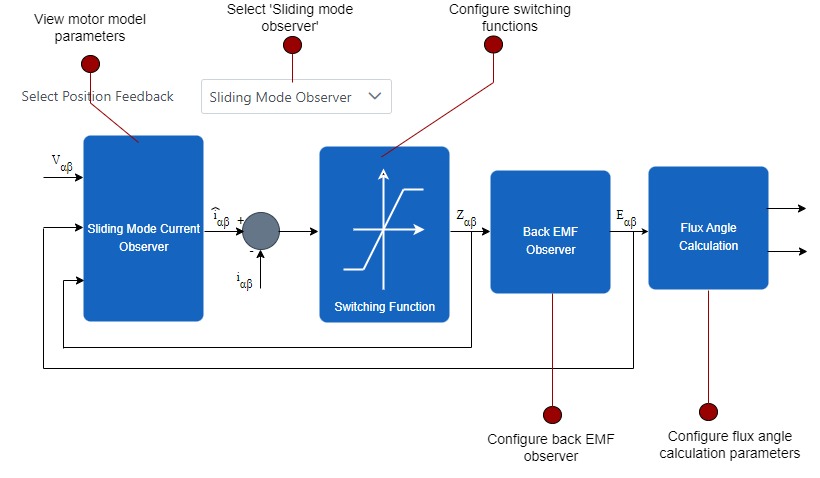
The Sliding Mode Observer (SMO) uses a non-linear switching function to estimate rotor position and speed. Its robustness against parameter variations makes it ideal for high-speed motor control.
For more details on the Sliding Mode Observer, refer to our application note AN4398.
Follow the steps below to configure the Sliding Mode Observer algorithm:
- Select Sliding Mode Observer from the 'Select Position Feedback' drop-down menu
2. View / configure the following parameters:
Sliding Mode Current Observer
- Click on the Sliding Mode Current Observer block to view motor parameters used in the Current Observer model.
- View the following fields in the configuration panel:
| Fields | Description |
|---|---|
| Line-neutral resistance (ohms) | View line to neutral resistance in ohms |
| Line-neutral direct-axis inductance Ld (Henry) | View Line-neutral quadrature-axis inductance Ld (Henry) |
| Line-neutral quadrature-axis inductance Lq (Henry) | View Line-neutral quadrature-axis inductance Lq (Henry) |
| Pole pairs | View pole pairs |
- If the values are 0, go to Motor GUI to select or configure motor parameters.
Switching Function
- Click on the Switching function block to configure the Ed boundary and gain values of the current observer.
- Set the following fields in the configuration panel:
| Fields | Description |
|---|---|
| Boundary | Boundary value for the non-linear switching function |
| Gain | Gain value for the non-linear switching function |
BEMF Observer
- Click on the BEMF Observer block to configure the BEMF pole location.
- Set the following fields in the configuration panel:
| Fields | Description |
|---|---|
| Pole location | Pole location of the BEMF observer |
Flux Angle Calculation
- Click on the Flux Angle Calculation block to configure the PLL used to determine the flux angle from BEMF signals.
- Set the following fields in the configuration panel:
| Fields | Description |
|---|---|
| Cut-off Frequency | Set the cut-off frequency of the SRF PLL used for angle and speed estimation |
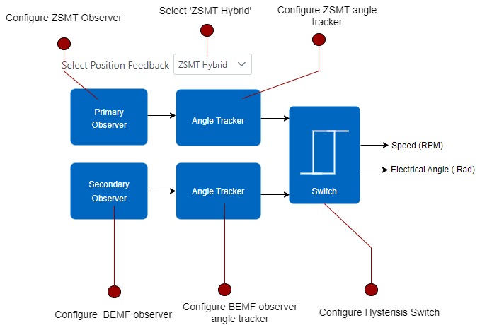
Setting-up ZSMT Hybrid based position sensing
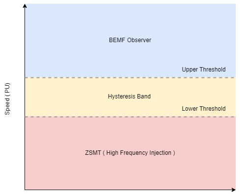
This method combines two techniques for rotor position and speed estimation:
- ZSMT with High-Frequency Injection (HFI) for low-speed control: At low speeds, high-frequency signals are injected, and the rotor position is determined using the zero-sequence response.
- Back EMF Observer with PLL for high-speed control: Using back EMF signals to estimate rotor position as speed increases.
A hysteresis band ensures smooth transitions between these methods, preventing instability around the crossover speed.
Follow the steps below to configure the Sliding Mode Observer algorithm:
- Select ZSMT Hybrid from the 'Select Position Feedback' drop-down menu
2. Set the primary (ZSMT observer) algorithm:
- Configure ZSMT HFI parameters:
-
- Click on the **Primary Observer** block to configure ZSMT HFI parameters.
- Set the following fields in the configuration panel:
| Fields | Description |
|---|---|
| HFI Pulse Amplitude | Set the HFI pulse amplitude in volts |
- Configure ZSMT Observer angle tracking loop and polarity correction:
-
- Click on the **Primary Angle Tracker** block to configure ZSMT HFI parameters.
- Set the following fields in the configuration panel:
| Fields | Description |
|---|---|
| Tracking loop type | Select the type of the selected PLL |
| Tracking loop tuning factor | Set the tracking loop tuning factor. In control systems, this indicates the error gain of the PLL system |
| Tracking loop cut-off frequency | Set the tracking loop cut-off frequency in Hertz |
| IPC pulse amplitude | Initial position correction pulse amplitude (in Volts) |
| IPC pulse duty (in ms) | Initial position correction pulse duty (in ms) |
| IPC pulse duration (in ms) | Initial position correction duration (in ms) |
3. Set the secondary (Classical Microchip Sensorless) algorithm:
- Configure Classical Microchip Sensorless observer.
- Configure Classical Microchip Sensorless angle tracking loop:
-
- Click on Secondary Angle Tracker to configure the BEMF observer PLL.
- Set the following fields in the configuration panel:
| Fields | Description |
|---|---|
| Tracking loop type | Select the type of the selected PLL |
| Tracking loop tuning factor | Set the tracking loop tuning factor. In control systems, this indicates the error gain of the PLL system |
| Tracking loop cut-off frequency | Set the tracking loop cut-off frequency in Hertz |
4. Set the hysteresis switch:
- Configure the upper and lower threshold of the hysteresis band:
-
- Click on the Switch block to configure the upper and lower threshold of the hysteresis band.
- Set the following fields in the configuration panel:
| Field | Description |
|---|---|
| Lower Threshold (0-1) | Defines the lower threshold value in per unit (PU) format, where 0 represents zero speed and 1 represents maximum speed. |
| Upper Threshold (0-1) | Defines the upper threshold value in per unit (PU) format, where 0 represents zero speed and 1 represents maximum speed. |
Kindly contact Microchip Local Sales for more details.
Setting-up Encoder based position sensing
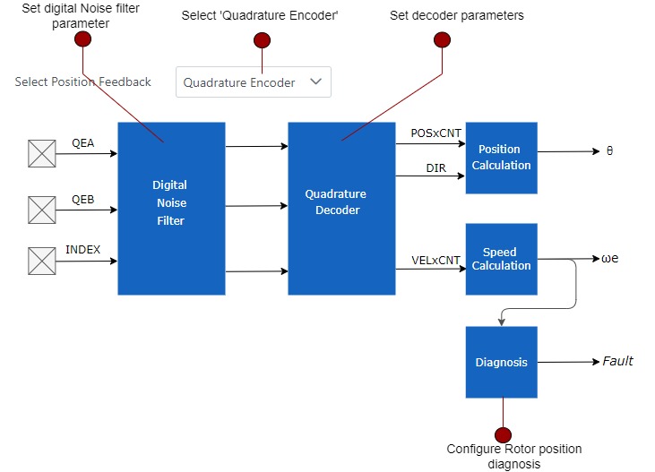
The Encoder-Based Position Sensing method directly measures the rotor position and speed using an optical or magnetic encoder attached to the motor shaft. This approach provides high accuracy and resolution, making it ideal for precise motion control applications. Its main advantages are reliable real-time feedback and simplicity in setup, as it eliminates the need for complex estimation algorithms.
For more details on encoder-based position sensing, refer to our application note AN2757
Follow the steps below to configure the Sliding Mode Observer algorithm:
1. Select Quadrature Encoder from the 'Select Position Feedback' drop-down menu.
2. Configure the Digital Noise Filter:
-Click on the Digital Noise Filter block to configure the minimum number of clock counts during which any consecutive signal changes are ignored.
-Set the following fields in the configuration panel:
| Field | Description |
|---|---|
| Filter Count | Number of clock counts during which any consecutive signal changes are ignored. |
3. Configure the Quadrature Decoder:
-Click on the Quadrature Decoder module to configure / view encoder counts per electrical rotation of the motor.
-Set the following fields in the configuration panel:
| Field | Description |
|---|---|
| Pulse Per Electrical Rotation | Set / view encoder counts per electrical rotation of the motor |
- If the values are 0, go to Motor GUI to select or configure the sensor interface of motor parameters.

