2.2 Hardware Setup for Raspberry Pi Touch Display 2
Connect the display to the host
using a compatible MIPI DSI connector. For this setup, a 34-to-15-pin MIPI display
connector maps the SAMA7D65’s 34-pin MIPI DSI port to the 15-pin connector of the
Raspberry Pi Touch Display 2.
Use a USB-C type cable to
connect a compatible power source (such as a USB-C wall adapter or a computer USB
port) to J3, ensuring the supply meets the SAMA7D65-Curiosity board’s 5V
requirement.
Connect the 5V and GND pins of
the display to the mikroBUS™ 2 5V and GND pins on the SAMA7D65-Curiosity board.
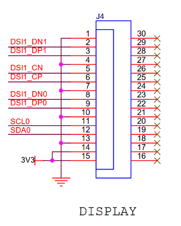
Pins 14 and 15 of the 15-pin MIPI
DSI connector on the Microchip MIPI display adapter are soldered to a 3.3V rail,
connected to the J26 mikroBUS 2 - 3.3V pin of the SAMA7D65-Curiosity board.
Note: Pins 14 and 15 (typically, DSI power-related lines) are not
directly powered via the 3.3V rail on the Microchip 15-to-34-pin DSI adapter, as shown
below:
The online versions of the documents are provided as a courtesy. Verify all content and data in the device’s PDF documentation found on the device product page.