
16.1 Functional Description
(Ask a Question)This section describes the implementation details of the Stepper Theta Generation.
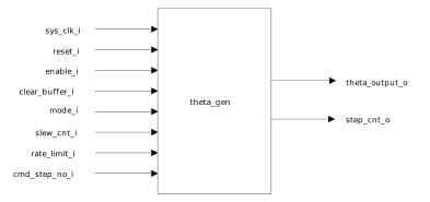
The following figure shows the system-level block diagram of the Stepper Theta Generation.
The profile of the stepper theta output and resultant current for various micro-stepping options are shown through the following figures.
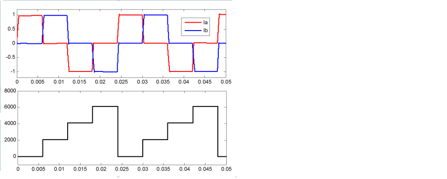
The following figure shows the theta generation in motor phase currents for half step mode.
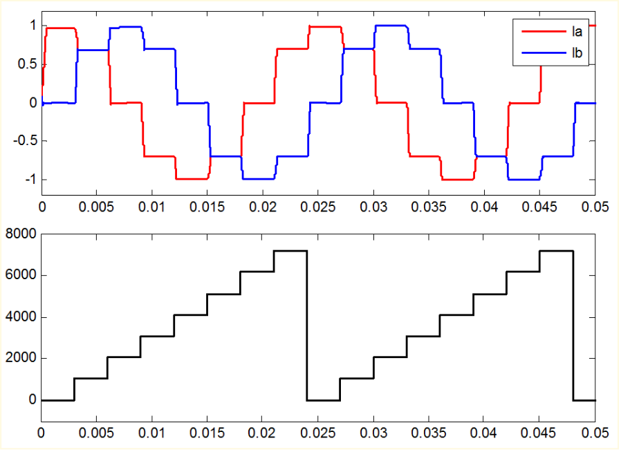
The following figure shows the theta generation motor phase currents in quarter step mode.
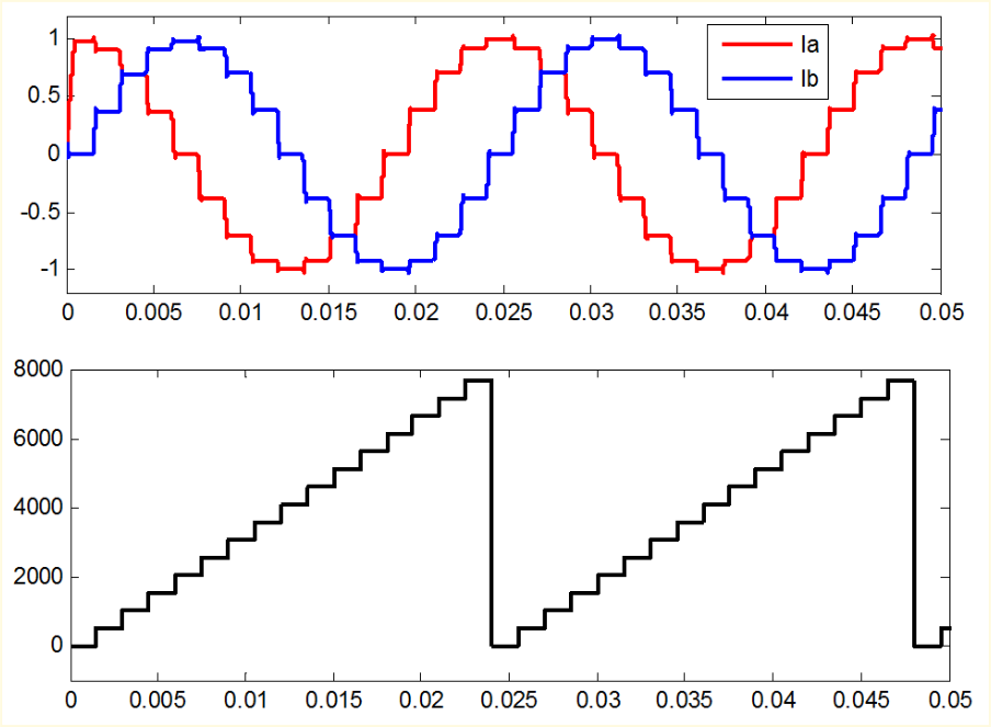
The following figure shows the theta generation motor phase currents in 1024 micro-stepping mode.
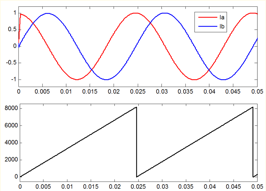
The level of micro stepping is decided by the rate limit input and must be an exponent of 2. The slew count input, then decides the speed at which theta value is updated. The output theta is generated till the command number of steps are met and then theta is held at last updated value until command steps changes. However, in speed mode, the output theta is continuously updated.