
47.6.3.3 Dithering Operation
The TCC supports dithering on Pulse-width or Period on a 16, 32 or 64 fractional clock cycle base.
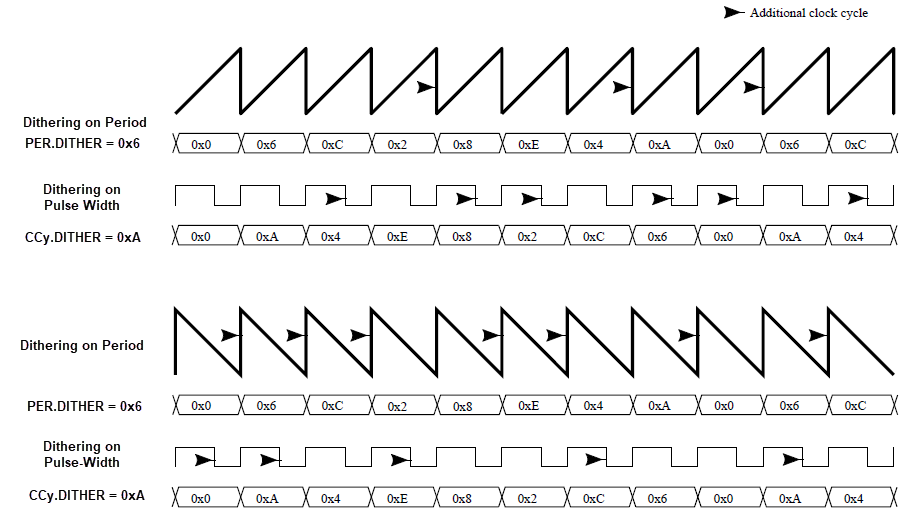
Dithering consists in adding some extra clock cycles on some PWM cycles, to improve the accuracy of the average output pulse width and period. The extra clock cycles are added on some of the compare match signals, one at a time, through a "blue noise" process that minimizes the flickering on the resulting dither patterns.
Dithering is enabled by writing the corresponding configuration in the Resolution bits in CTRLA register (CTRLA.RESOLUTION (CTRLA <6:5>) ) and gives user three different options::
- DITH4 dithering resolution is based on the overflow of a 4 bit-counter
- DITH5 dithering resolution is based on the overflow of a 5 bit-counter
- DITH6 dithering resolution is based on the overflow of a 6 bit-counter
The least significant bits of COUNT, PER and CCy registers are used to improve accuracy of output pulse width and period. These bits are called DITHERCY bits.
The remaining bits of COUNT, PER and CCy registers define the compare value for the normal operation. The DITHERCY bits of COUNT, PER and CCy define the increment on respective dithering counter (COUNT, PER or CCy) registers to perform on each PWM cycle. If the value of dithering counter in CC register is '0' output pulse width dithering will be disabled. Similarly, if the value of dithering counter in PER register is '0' period dithering will be disabled.
Dithering works as described below:
- In up-counting operation an extra clock cycle is inserted on each dithering counter overflow
- In down-counting operation an extra clock cycle is inserted on each PWM cycles, except when a dithering counter overflow occur
The pseudo code, giving the extra cycles insertion regarding the cycle is:
int extra_cycle(resolution, dithercy, cycle){
  int MASK;
  int value
  switch (resolution){
    DITH4: MASK = 0x0f;
    DITH5: MASK = 0x1f;
    DITH6: MASK = 0x3f;
  }
  value = cycle * dithercy;
  if (((MASK & value) + dithercy) > MASK)
    return 1;
 return 0;
}
Dithering on Period
Writing DITHERCY in PER will lead to an average PWM period configured by the following formulas.
DITH4 mode:
If DITH4 mode is enabled for the period the 6 least significant bits from PER and COUNT registers correspond to the period DITHERCY value, rest of the bits correspond to PER or COUNT value.
DITH5 mode:
If DITH5 mode is enabled for the period the 6 least significant bits from PER and COUNT registers correspond to the DITHERCY value, rest of the bits correspond to PER or COUNT value.
DITH6 mode:
If DITH6 mode is enabled for the period the 6 least significant bits from PER and COUNT registers correspond to the DITHERCY value, rest of the bits correspond to PER or COUNT value.
Dithering on Pulse-Width
Writing DITHERCY in CCy will lead to an average PWM pulse width configured by the following formulas.
DITH4 mode:
If DITH4 mode is enabled for pulse width the 6 least significant bits from CCy and COUNT registers correspond to the output pulse width DITHERCY value, rest of the bits correspond to CCy or COUNT value.
DITH5 mode:
If DITH5 mode is enabled for pulse width the 6 least significant bits from CCy and COUNT registers correspond to the output pulse width DITHERCY value, rest of the bits correspond to CCy or COUNT value.
DITH6 mode:
If DITH6 mode is enabled for pulse width the 6 least significant bits from CCy and COUNT registers correspond to the output pulse width DITHERCY value, rest of the bits correspond to CCy or COUNT value.