
5.3.3 I/O Pin Window
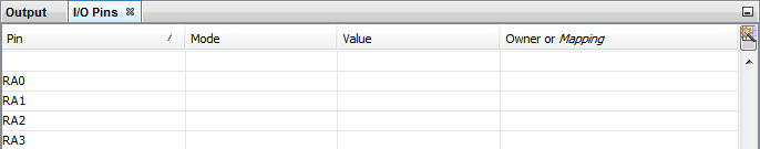
The I/O Pin window is helpful during debugging of a simulator project. To access the window, select Window>Simulator> I/O Pin. The display shows the current state of a pin and allows you to set a pin value.
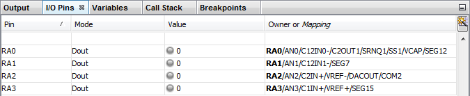
Before a debug session has begun, only the “Pin” column has an values (in the first figure). During a debug session, the other column values are displayed (see the second figure). When you switch projects, the pin displayed in the I/O Pin window will change accordingly.
Changing the Display
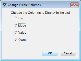
Each pin occupies a row in the display. A row can be moved up and down and the columns can be reordered by dragging them. To select which columns to view, click the button on the upper right corner next to the “Owner or Mapping” column to open this dialog.
Viewing and Changing Fields
The I/O Pin window had the following fields in each column.
| Field | Description |
|---|---|
| Pin | All the signal names form the data sheet for the selected device. |
| Mode | Displays the mode of the selected pin.
This is determined by the associated SFR values. You cannot edit this
field. The modes are:
|
| Value | Displays the value of the pin. If an analog pin, enter the voltage value. If a digital pin, select 0 or 1 from the drop-down list. |
| Owner or Mapping | Displays which signal is driving the
pin (owner) or the specific mapping for the selected pin. This is
determined by the associated SFR values. You cannot edit this field. For a non-remappable signal, the bolded signal is the owner. For example, in RB3/CN7/RP3/C1IN+/AN5, the owner is RB3. For a remappable signal, it is the pin that is being mapped to. An output remappable signal may be mapped to multiple RPs. |
Working with Analog
To work with analog pins:
- Ensure the pins are set to be analog, and not digital I/O.
- Set the pins to be inputs.
- Set voltages on reference pins.
See your device data sheet to determine how to set these for your device.
To enter analog values:
- Enter an analog input value into the “Value” field of the pin(s). See your device data sheet for applicable values.
- Continue with your debug session execution and the ADC will convert the value on the input pin(s).