5.3.1 Monitor Ports State
The Port State Overview page provides an entire system overview in a single web page. It is the web page presented to the user when browsing to unit IP address.
The Port State Overview page has the following parameters:
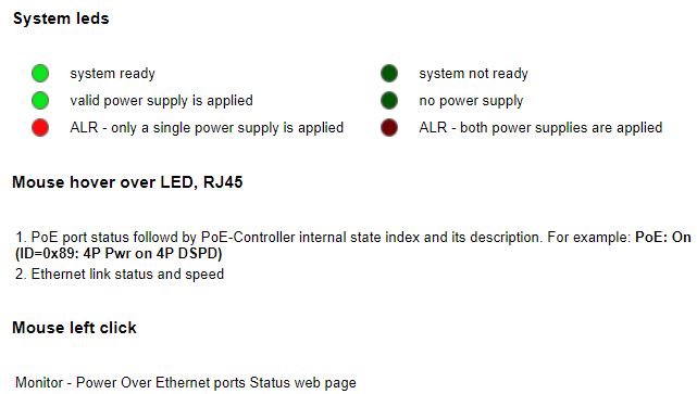
- Ports—Front Panel
Figure 5-11. GUI 

- Ports - Network Status
- #: Port number.
- Type: Copper. Ports 1–8 are Gigabit copper ports
- Status:
- ---: Port is enabled. Link is down.
- Up: Port is enabled. Link is up.
- Disabled: Port is disabled
- Speed: Port link speed: 10 Mbps, 100 Mbps, 1 Gbps,
- Aggregation (Aggr) Ports: Reports configured aggregation ports. For example: P1, P2.
- Transmit: Average transmit data rate in Kbit, Mbit per second
- Receive: Average receive data rate in Kbit, Mbit per second
- System Name: Remote Network device name as advertised over LLDP/CDP
- System Description: Remote Network system description as advertised over LLDP/CDP
- IP Address: Remote Network device IP-Address as advertised over LLDP/CDP
- Ports - PoE Status
- PoE-BT Port Type: PoE port max power configuration. Power to PD is shut down when PD tries to exceed the limit.
- Type4-90W: PoE-BT up to 90W on four pairs. Up to 45W on two pairs.
- Type3-60W: PoE-BT up to 60W on four pairs. Up to 30W on two pairs.
- Type3-30W: PoE-BT up to 30W on four pairs. Up to 30W on two pairs.
- Type3-15W: PoE-BT up to 15W on four pairs. Up to 15W on two pairs.
- Power Management Mode: Power management configuration mode effecting how PD class, power consumption effects the unit overall free available power.
- Dynamic: PoE port dynamic real time power consumption is deducted from overall PoE free power budget ignoring PD class or PoE port maximum power.
- Static: PoE port type power configuration (as Type4-90W) is deducted from overall PoE free power budget after PoE port is turned on, ignoring PD actual power consumption. Next PD may not be turned on when free available power is lower than PD requested power. Initial PD requested power is based on PD class, PD Auto-Class.
- Hybrid: Mixture of dynamic and static power management based on PD advertising its power requirements by sending LLDP IEEE 802.3 Power through MDI TLV protocol.
Every PoE port configured as Hybrid acts as if it was configured as Dynamic, if it has not received any Power Over-MDI TLV within LLDP packet sent by the PD. After receiving IEEE
802.3 Power through MDI TLV, the port switches to Static Power mode limiting PoE port maximum power as per the PD requested power plus user configured cable loss based on user cable length configuration. Static PoE port maximum power may change based on PD LLDP IEEE 802.3 Power through MDI TLV advertised values.
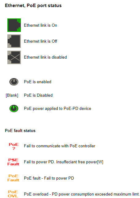
- Status—reports the latest PoE port status
- ---: PoE port is enabled. No PoE-PD
- On: PoE power is applied to PD
- Disabled: PoE is disabled (non-related to Ethernet data link state)
- Overload: PD power consumption exceeded its maximum limit. Power was shut down.
- Fault: Fail to turn on connected PD device. The following are the possible reasons:
- Non-standard PD is connected
- PD class error
- PD underload (PD power consumption is too low)
- Shortage or invalid capacitor value
- PD was disconnected (temporary recovery from underload)
- PSE Fault. Not enough free available power to turn on PD device. Another rare possible reason: Power supply voltage is out of range. Voltage is injected into the Ethernet port. Port over temperature condition.
- Requested Power: PoE PD requested power based on PD Class. Class 8 = 90W, class 5, 5 = 90W, class 6 = 60W, class 4, 4 = 60W, class 4 = 30W, class 3 = 15W, class 2 = 7W, class 1 = 4W, class 0 = 15W.
- Assigned Power: The maximum power that was assigned to the PD. Trying to consume above this limit causes the PD to be turned off. When enabling Legacy PD_Class Mode, assigned PD class may differ from measured PD class, leading to Assigned-Power to differ from the Requested-Power. The difference in power is due to the following reasons:
- Demotion: Free available power is less than the PD requested power. PoE-BT uses the demotion option to offer a lower power value to the PD. If PD agrees to the lower power value, then it is turned on with lower power limit.
- PoE Port maximum Power: PoE port maximum power configuration lower than the newly inserted PD power class. For example, a 90W PD class-8 being connected to PoE port configured as Type3-60W.
- Delivered Power: Temporarily PD power consumption
- Assigned Class: PD maximum power consumption is determined by the class it is being assigned by the PoE controller (8=90W/ 5, 5=90W/ 6=60W/ 4, 4=60W/ 4=30W/ 3=15W/2= 7W/1=4W/0 = 15W). Most of the time PD Assigned-Class matches PD-Measured-Class. PD-Assigned-Class differs from PD-Measured-Class in one of the following scenarios:
- PoE Power Demotion: Per IEEE 802.3bt specification, when PoE port maximum available power is less than PD requested power, the PoE port may offer the PD a lower maximum power value. It is up to the PD to decide if to accept the new offer agreeing to consume less power. For example, PD class-8 (90W) is being connected while PoE-Port has only 60W spare power left. Port offers PoE class-6 (60W). If PD accepts the offer, then Measured-Class is class-8 while Assigned-Class is class-6.
- Legacy PD-Class Mode = PoH. Port Mode = Plus. PoE-AT DSPD PD class 4, 4 is given 90W as if it is class 5, 5 (2×45W). PoE-AT SSPD PD class 4 is given 45W as class 5.
- Legacy PD-Class Mode = Ignore PD-Class. Port Mode =Type4-90W. Any DSPD class- x, x is given 90W as if it is class 5, 5 (2×45W). SSPD PD class-x is given 45W as if it is class 5.
- Legacy PD-Class Mode = Ignore PD-Class. Port Mode=Type3-60W. Any DSPD Class-x, x is given 60W as if it is class 4, 4 (2×30W). SSPD PD class-x is given 30W as if it is class 4.
- PD Measured Class: Remote PoE-PD measured Class 1–8 for SSPD, or Class 0,0, Class 5, 5 for DSPD
- PD Auto Class Support: Report if remote PoE-BT PD device advertise it is supporting PoE Auto Class regardless to unit Auto Class configuration. When enabled and supported by the PoE-PD device, PoE port maximum power allocation is determined by the power consumed by PD during the Auto Class negotiation phase instead of the PD class.
- PD Requested Power over LLDP: When supported by remote PoE-PD; Report remote PoE PD requested power using LLDP Power Over-MDI. If PoE-LLDP is disabled, (N/A) appears
to the right or PD request power, ignoring PD request power using only PD class for determining PoE power request. When PoE-LLDP is enabled, PD PoE power request over LLDP replaces PoE PD class. However, it never exceeds the PD class maximum power. Cable loss based on cable length configuration is added on top of PD LLDP requested power. PoE power management configuration mode controls how much power is deducted from unit free available power.
- PoE-BT Port Type: PoE port max power configuration. Power to PD is shut down when PD tries to exceed the limit.
- System—Status
- Total Power Usage: Total power consumption by all PoE ports
- Total Allocated Power: Total power allocated to all active PoE ports. PoE port power management mode configuration effects the total allocated power
- Free Available Power: The free available power left to power additional PoE port, or before turning off active PoE PD due to lack of free available power.
- Power Supply Voltage: PoE power supply voltage
