The following figure illustrates the 3D radiation pattern of the PCB antenna at
2438 MHz.
Figure 7-1. PCB Antenna 3D Radiation Pattern At
2438 MHz(1)
The preceding figure illustrates the
typical radiation pattern with BM83 module on the 45 mm x 45
mm BM83 Carrier Board.
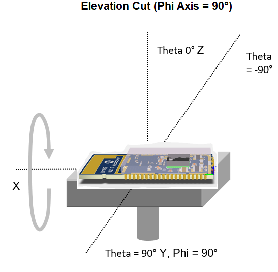
The following figure illustrates the module orientation for antenna
radiation pattern.Figure 7-2. Module Orientation for Radiation
Pattern
Figure 7-3. Polar Plots(1)
The preceding figure illustrates the typical radiation pattern with BM83 module on the 45 mm x 45 mm BM83 Carrier Board.
The following table provides the characteristics of PCB antenna with BM83 Module mounted on BM83 Carrier
Board, plugged into BM83 EVB.
Table 7-1. BM83
PCB Antenna Characteristics
Parameter
Value
Frequency
2400 MHz to 2480 MHz
Peak Gain
3.5 dBi
Efficiency
80%
The online versions of the documents are provided as a courtesy. Verify all content and data in the device’s PDF documentation found on the device product page.