
14.3.1 TX (Send Request)
- First step in
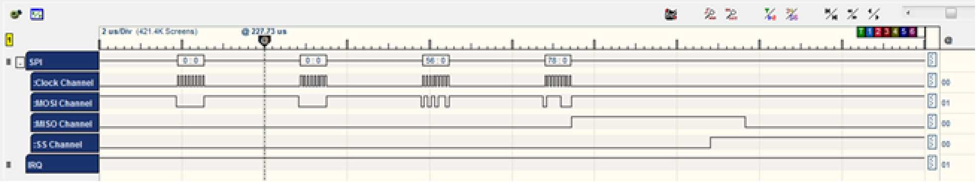
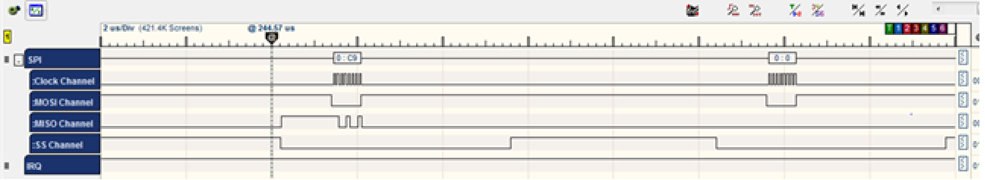
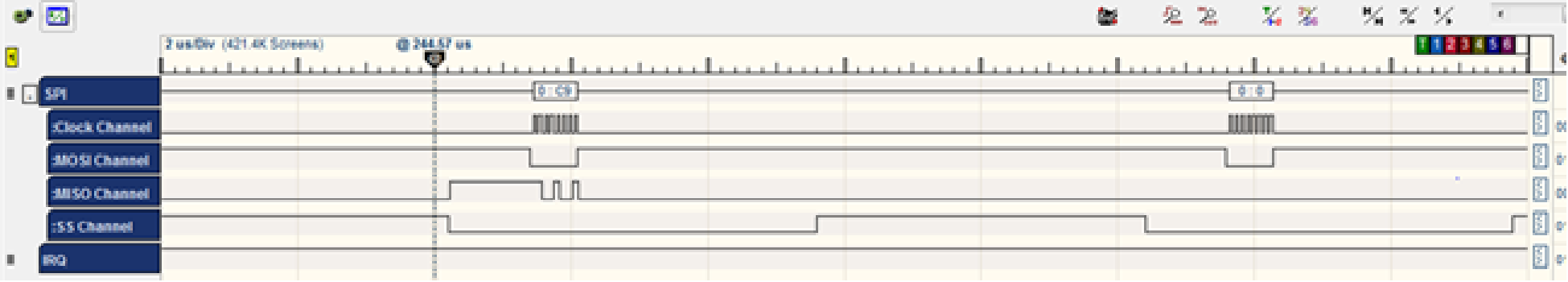
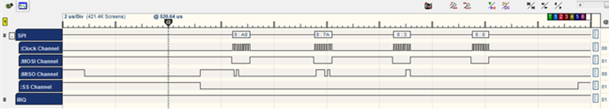
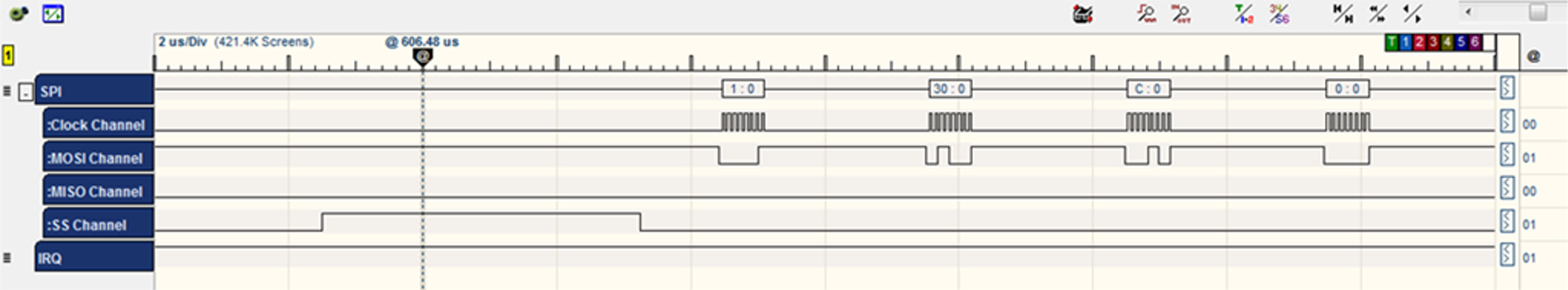
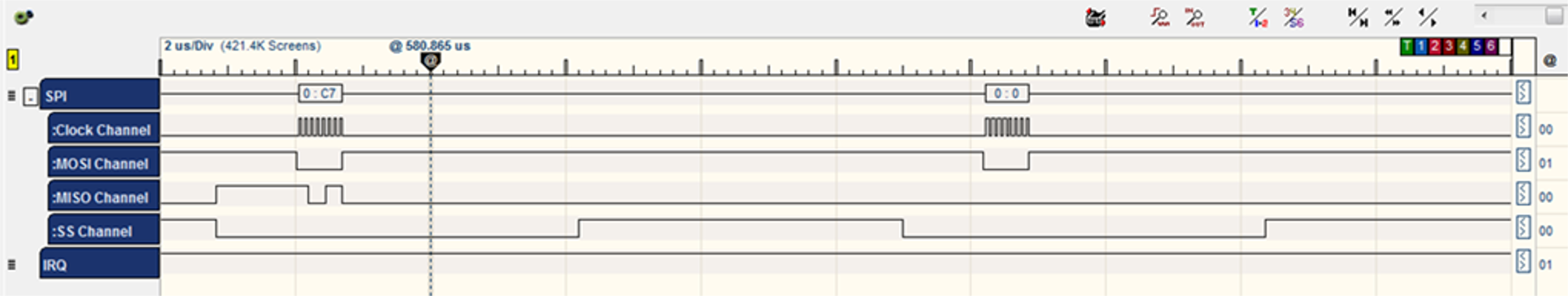
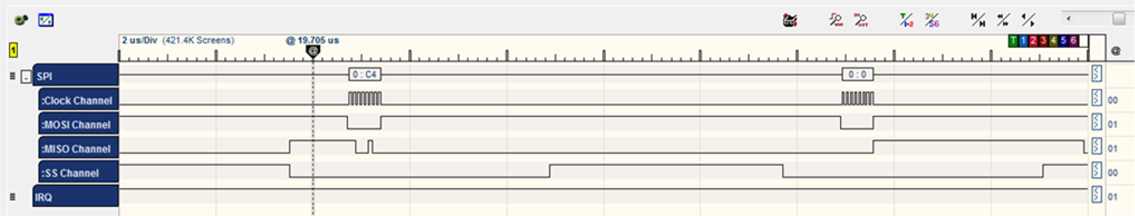
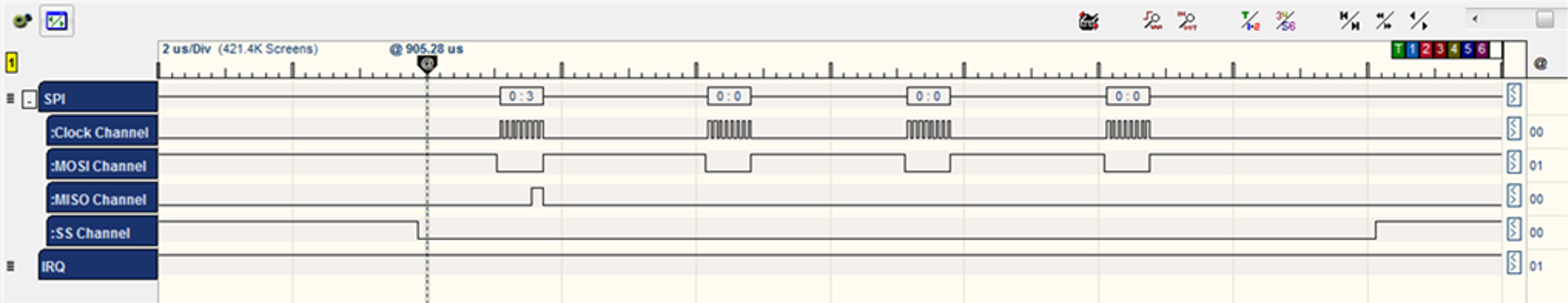
hif_send() APIis to wake up the chip.sint8 nm_clkless_wake(void) { ret = nm_read_reg_with_ret(0x1, ®); /* Set bit 1 */ ret = nm_write_reg(0x1, reg | (1 << 1)); // Check the clock status ret = nm_read_reg_with_ret(clk_status_reg_adr, &clk_status_reg); // Tell Firmware that Host waked up the chip ret = nm_write_reg(WAKE_REG, WAKE_VALUE); return ret; }Command CMD_INTERNAL_READ: 0xC4 /* internal register read */ BYTE [0] = CMD_INTERNAL_READ BYTE [1] = address >> 8; /* address = 0x01 */ BYTE [1] |= (1 << 7); /* clockless register */ BYTE [2] = address; BYTE [3] = 0x00;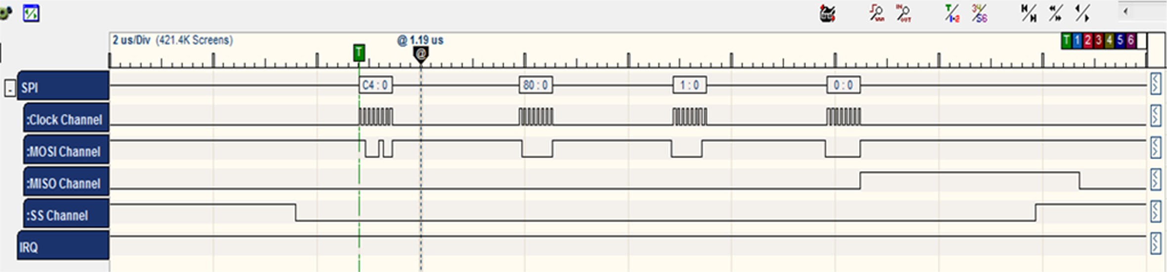
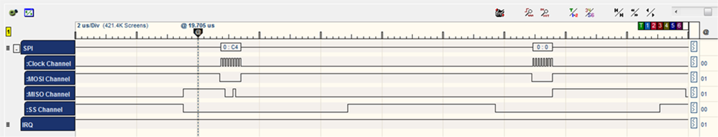
- The WINC acknowledges the command by sending three bytes [C4] [0] [F3].

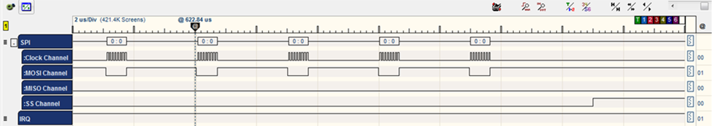
- The WINC chip sends the value of the register 0x01 which equals 0x01.
Command CMD_INTERNAL_WRITE: C3 /* internal register write */ BYTE [0] = CMD_INTERNAL_WRITE BYTE [1] = address >> 8; /* address = 0x01 */ BYTE [1] |= (1 << 7); /* clockless register */ BYTE [2] = address; BYTE [3] = u32data >> 24; /* Data = 0x03 */ BYTE [4] = u32data >> 16; BYTE [5] = u32data >> 8; BYTE [6] = u32data;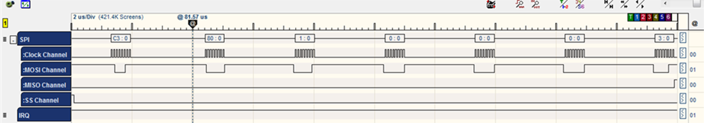
- The WINC acknowledges the command by sending two bytes [C3] [0].
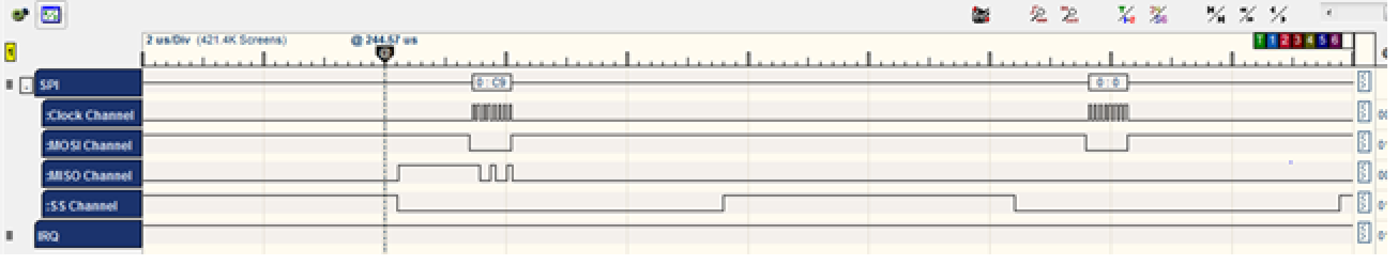
Command CMD_INTERNAL_READ: 0xC4 /* internal register read */ BYTE [0] = CMD_INTERNAL_READ BYTE [1] = address >> 8; /* address = 0x0F */ BYTE [1] |= (1 << 7); /* clockless register */ BYTE [2] = address; BYTE [3] = 0x00;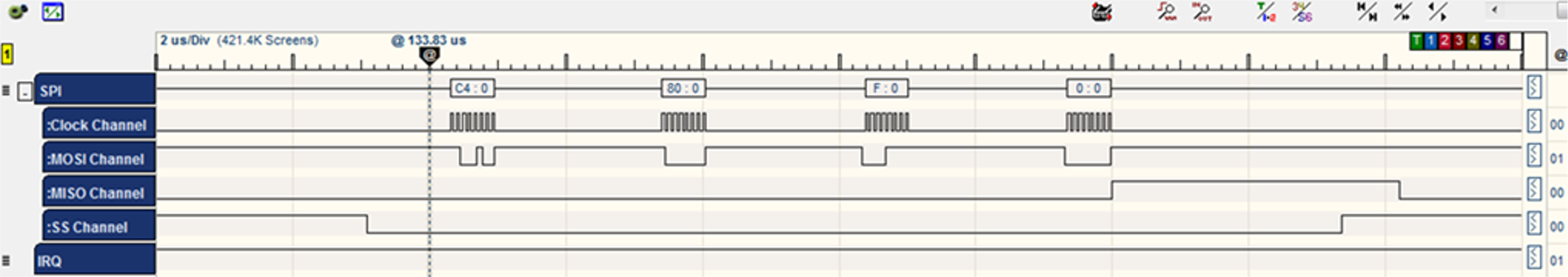
- The WINC acknowledges the command by sending three bytes [C4] [0] [F3].
- The WINC chip sends the value of the register 0x01 which equals 0x07.
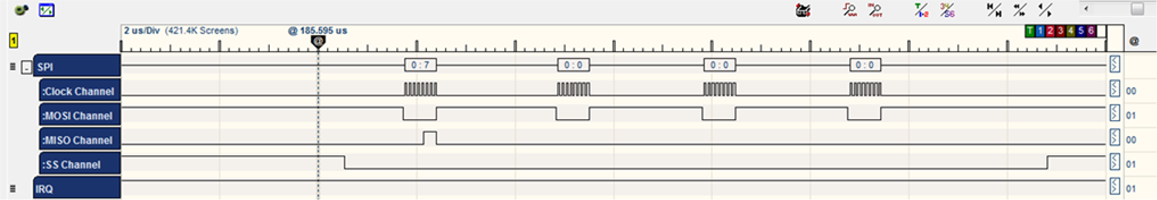
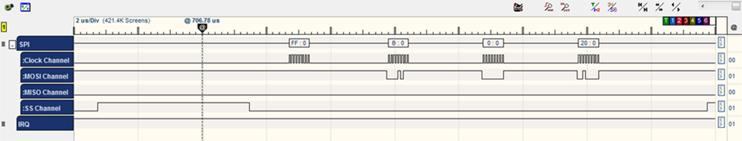
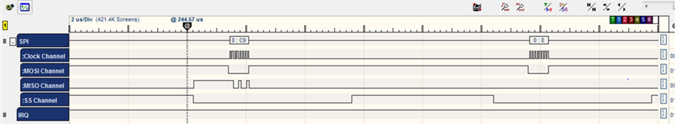
Command CMD_SINGLE_WRITE:0XC9 /* single word write */ BYTE [0] = CMD_SINGLE_WRITE BYTE [1] = address >> 16; /* WAKE_REG address = 0x1074 */ BYTE [2] = address >> 8; BYTE [3] = address; BYTE [4] = u32data >> 24; /* WAKE_VALUE Data = 0x5678 */ BYTE [5] = u32data >> 16; BYTE [6] = u32data >> 8; BYTE [7] = u32data;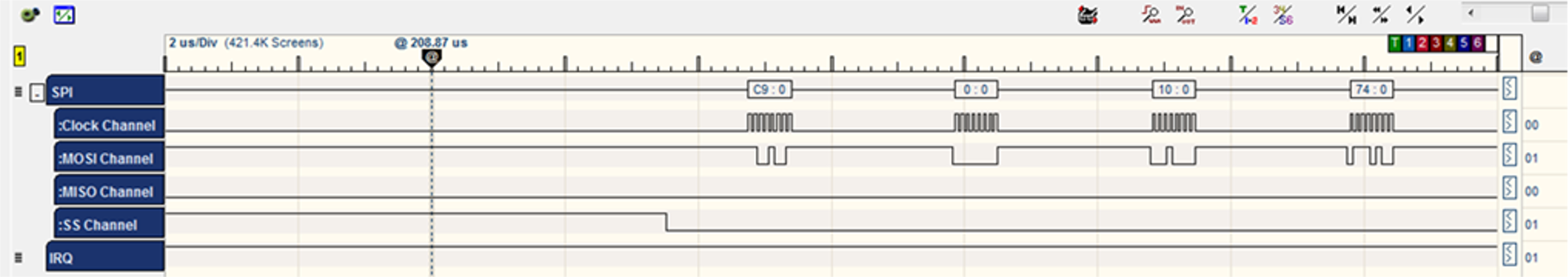
- The chip acknowledges the command by sending two bytes [C9] [0].
- At this point, HIF finishes executing the clockless wake up of the WINC chip.
- The HIF layer prepares and sets the HIF layer header to NMI_STATE_REG register (4 byte or 8 byte header describing the packet to be sent).
- Set bit '
1' of WIFI_HOST_RCV_CTRL_2 register to raise an interrupt to the chip.sint8 hif_send(uint8 u8Gid,uint8 u8Opcode,uint8 *pu8CtrlBuf,uint16 u16CtrlBufSize, uint8 *pu8DataBuf,uint16 u16DataSize, uint16 u16DataOffset) { volatile tstrHifHdr strHif; volatile uint32 reg; strHif.u8Opcode = u8Opcode&(~NBIT7); strHif.u8Gid = u8Gid; strHif.u16Length = M2M_HIF_HDR_OFFSET; strHif.u16Length += u16CtrlBufSize; ret = nm_clkless_wake(); reg = 0UL; reg |= (uint32)u8Gid; reg |= ((uint32)u8Opcode<<8); reg |= ((uint32)strHif.u16Length<<16); ret = nm_write_reg(NMI_STATE_REG,reg); reg = 0; reg |= (1<<1); ret = nm_write_reg(WIFI_HOST_RCV_CTRL_2, reg);Command CMD_SINGLE_WRITE:0XC9 /* single word write */ BYTE [0] = CMD_SINGLE_WRITE BYTE [1] = address >> 16; /* NMI_STATE_REG address = 0x108c */ BYTE [2] = address >> 8; BYTE [3] = address; BYTE [4] = u32data >> 24; /* Data = 0x000C3001 */ BYTE [5] = u32data >> 16; /* 0x0C is the length and equals 12 */ BYTE [6] = u32data >> 8; /* 0x30 is the Opcode = M2M_WIFI_REQ_SET_SCAN_REGION */ BYTE [7] = u32data; /* 0x01 is the Group ID = M2M_REQ_GRP_WIFI */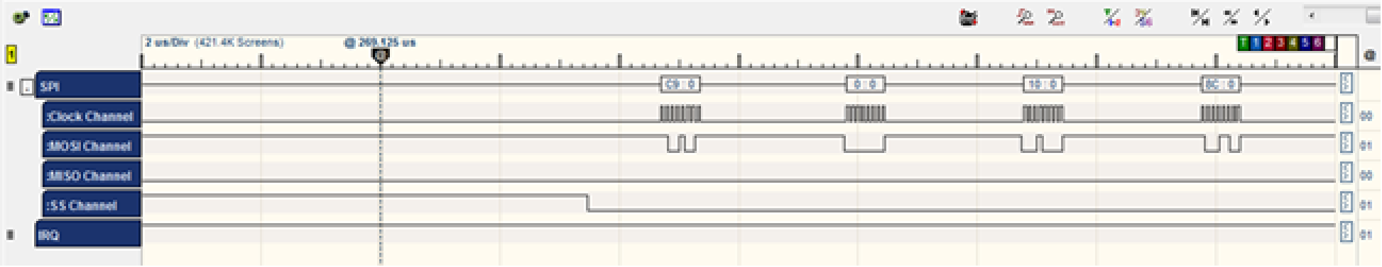
- The WINC acknowledges the command by sending two bytes [C9] [0].
Command CMD_SINGLE_WRITE:0XC9 /* single word write */ BYTE [0] = CMD_SINGLE_WRITE BYTE [1] = address >> 16; /* WIFI_HOST_RCV_CTRL_2address = 0x1078*/ BYTE [2] = address >> 8; BYTE [3] = address; BYTE [4] = u32data >> 24; /* Data = 0x02 */ BYTE [5] = u32data >> 16; BYTE [6] = u32data >> 8; BYTE [7] = u32data;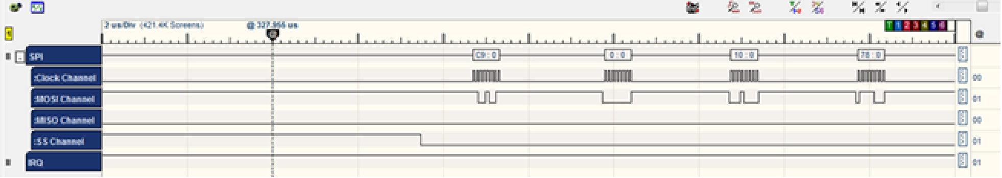

- The WINC acknowledges the command by sending two bytes [C9] [0].
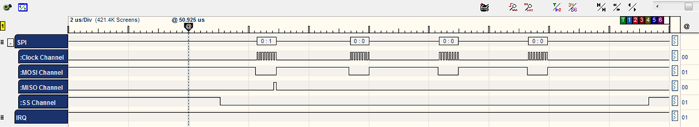
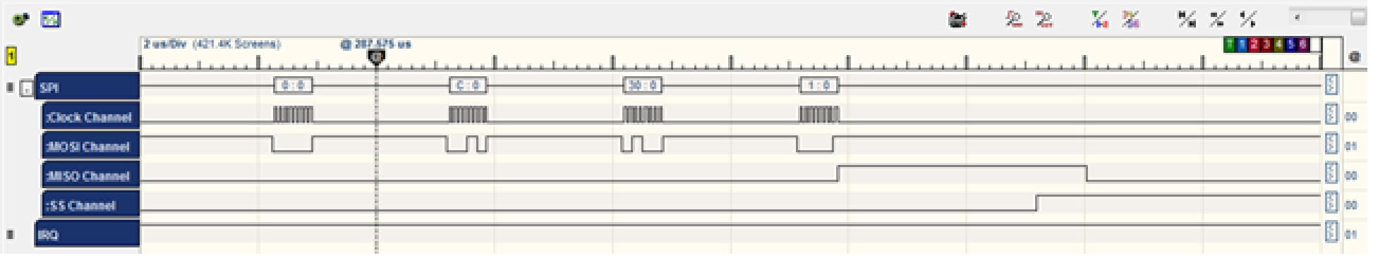
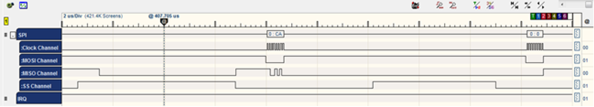
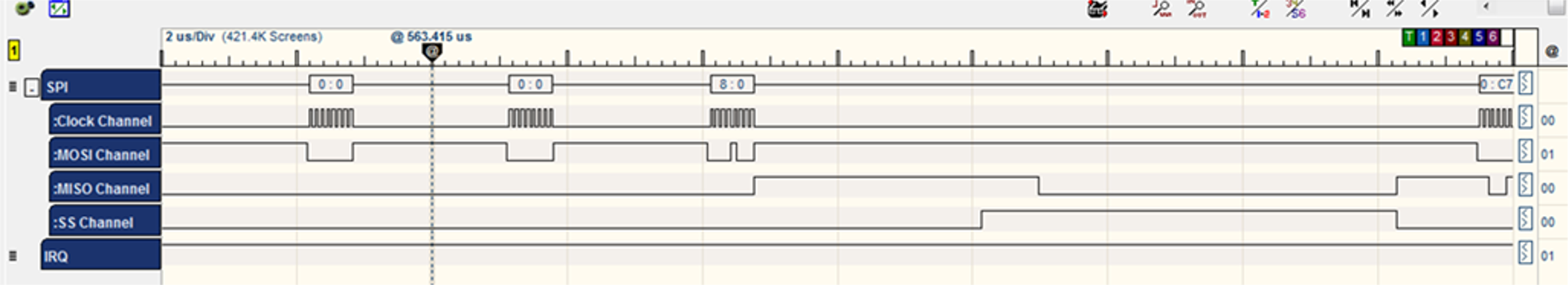
- Then HIF polls for DMA
address.
for (cnt = 0; cnt < 1000; cnt ++) { ret = nm_read_reg_with_ret(WIFI_HOST_RCV_CTRL_2,(uint32 *)®); if(ret != M2M_SUCCESS) break; if (!(reg & 0x2)) { ret = nm_read_reg_with_ret(0x150400,(uint32 *)&dma_addr); /*in case of success break */ break; } }Command CMD_SINGLE_READ: 0xCA /* single word (4 bytes) read */ BYTE [0] = CMD_SINGLE_READ BYTE [1] = address >> 16; /* WIFI_HOST_RCV_CTRL_2 address = 0x1078 */ BYTE [2] = address >> 8; BYTE [3] = address;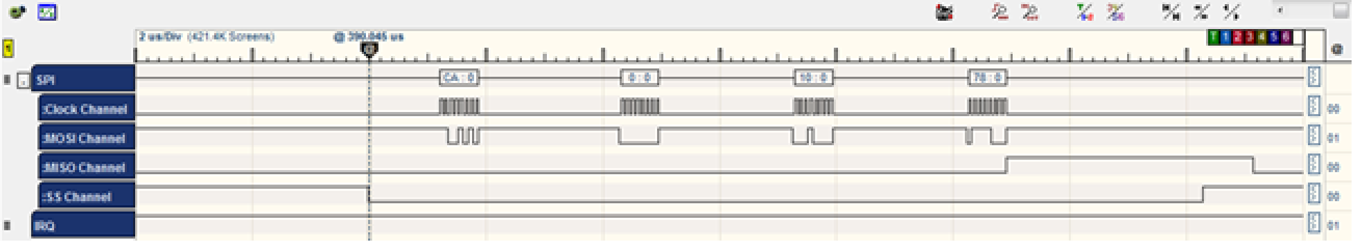
- The WINC acknowledges the command by sending three bytes [CA] [0] [F3].
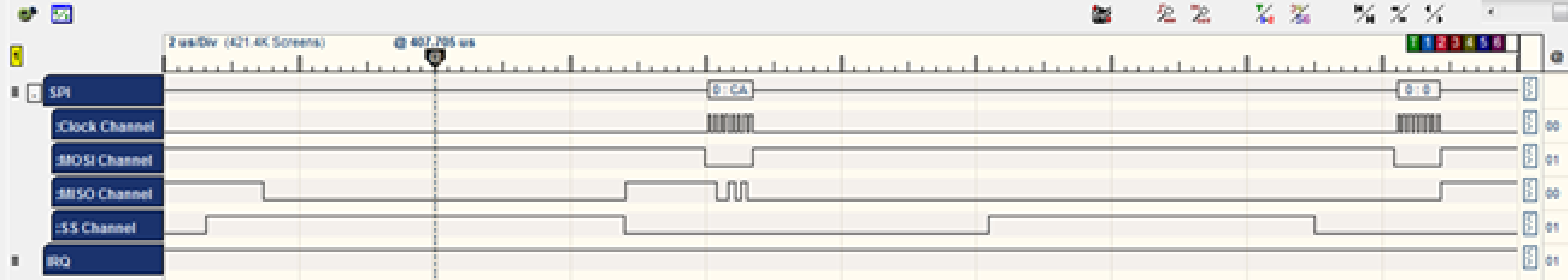
-
The WINC chip sends the value of the register 0x1078, which equals 0x00.
Command CMD_SINGLE_READ: 0xCA /* single word (4 bytes) read */ BYTE [0] = CMD_SINGLE_READ BYTE [1] = address >> 16; /* address = 0x1504 */ BYTE [2] = address >> 8; BYTE [3] = address;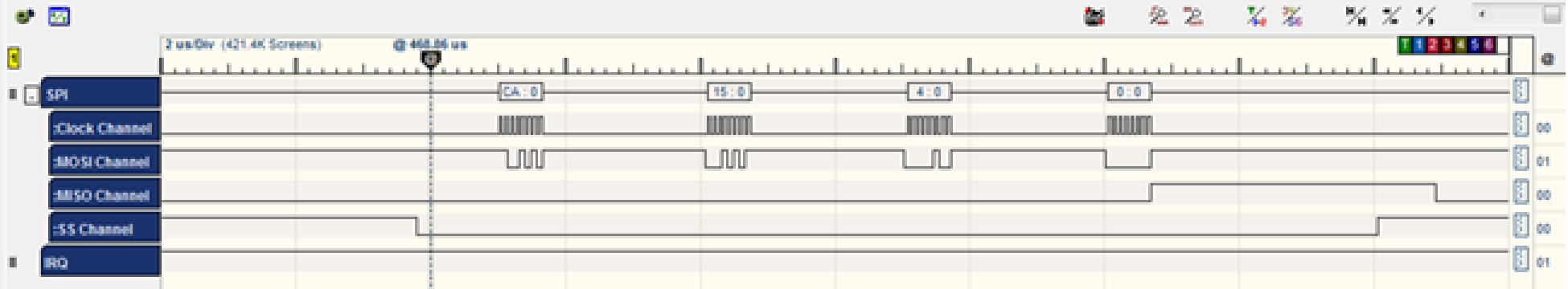
- The WINC acknowledges the command by sending three bytes [CA] [0] [F3].
- The WINC chip sends the value of the register 0x1504, which equals 0x037AA0.
- The WINC writes the HIF header to the DMA memory
address.
u32CurrAddr = dma_addr; strHif.u16Length=NM_BSP_B_L_16(strHif.u16Length); ret = nm_write_block(u32CurrAddr, (uint8*)&strHif, M2M_HIF_HDR_OFFSET);Command CMD_DMA_EXT_WRITE: 0xC7 /* DMA extended write */ BYTE [0] = CMD_DMA_EXT_WRITE BYTE [1] = address >> 16; /* address = 0x037AA0 */ BYTE [2] = address >> 8; BYTE [3] = address; BYTE [4] = size >> 16; /* size = 0x08 */ BYTE [5] = size >> 8; BYTE [6] = size;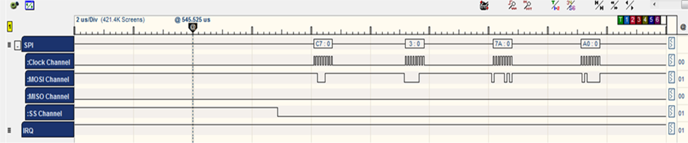
- The WINC acknowledges the command by sending three bytes [C7] [0] [F3].
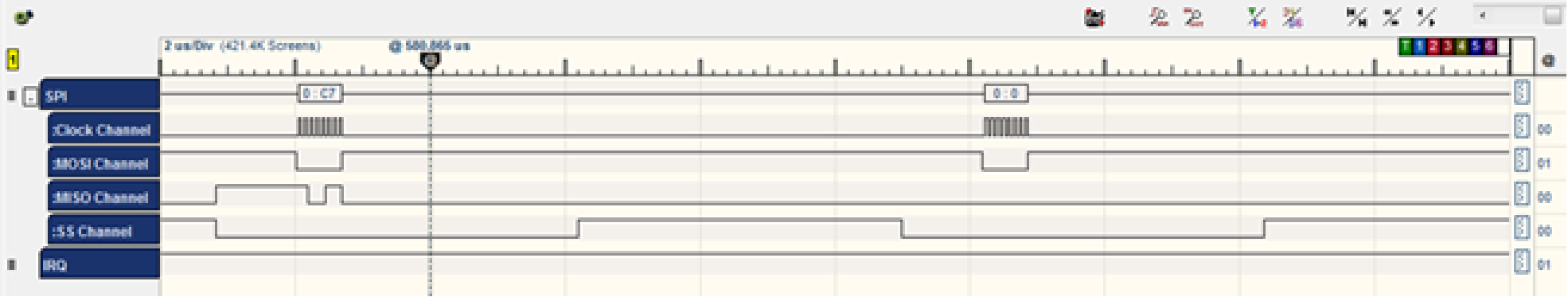
- The HIF layer writes the data.
- The HIF writes the Control Buffer data (part of the framing of the
request).
if (pu8CtrlBuf != NULL) { ret = nm_write_block(u32CurrAddr, pu8CtrlBuf, u16CtrlBufSize); if(M2M_SUCCESS != ret) goto ERR1; u32CurrAddr += u16CtrlBufSize; }Command CMD_DMA_EXT_WRITE: 0xC7 /* DMA extended write */ BYTE [0] = CMD_DMA_EXT_WRITE BYTE [1] = address >> 16; /* address = 0x037AA8 */ BYTE [2] = address >> 8; BYTE [3] = address; BYTE [4] = size >> 16; /* size = 0x04 */ BYTE [5] = size >> 8; BYTE [6] = size;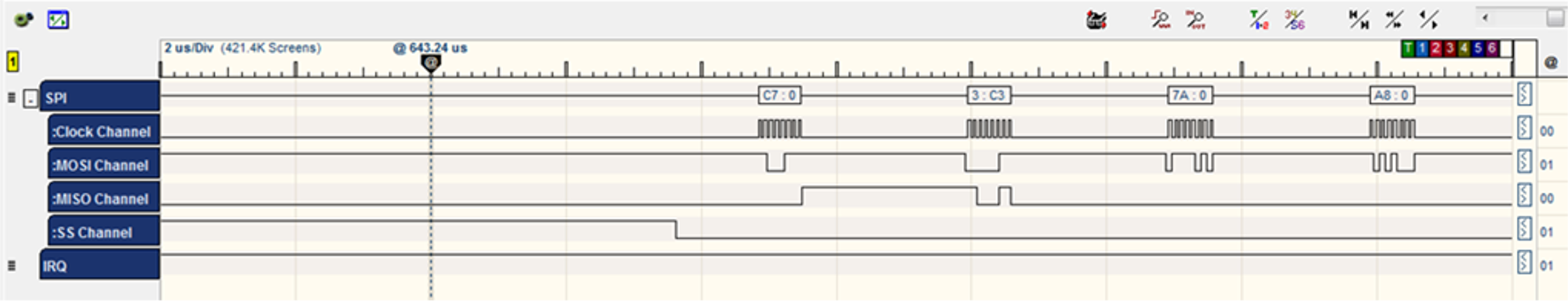
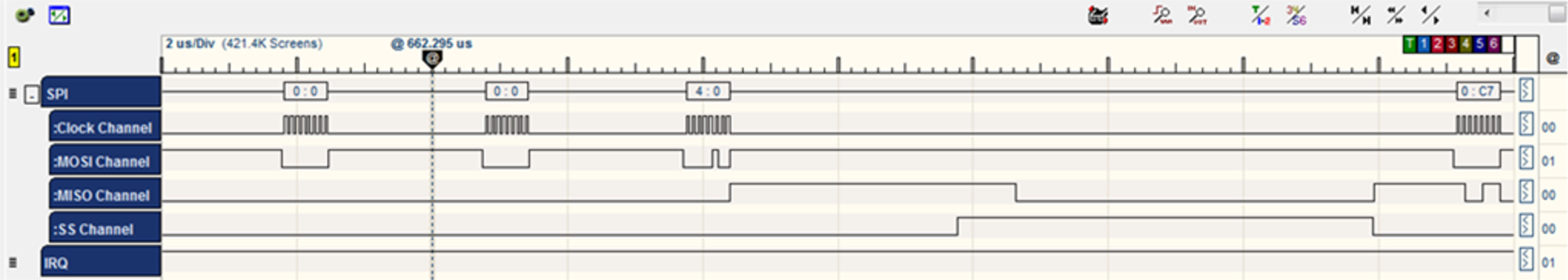
- The WINC acknowledges the command by sending three bytes [C7] [0] [F3].
- The HIF layer writes the data.
- The HIF finished writing the request data to
memory and is going to interrupt the chip notifying that host TX is
done.
reg = dma_addr << 2; reg |= (1 << 1); ret = nm_write_reg(WIFI_HOST_RCV_CTRL_3, reg);Command CMD_SINGLE_WRITE:0XC9 /* single word write */ BYTE [0] = CMD_SINGLE_WRITE BYTE [1] = address >> 16; /* WIFI_HOST_RCV_CTRL_3 address = 0x106C */ BYTE [2] = address >> 8; BYTE [3] = address; BYTE [4] = u32data >> 24; /* Data = 0x000DEA82 */ BYTE [5] = u32data >> 16; BYTE [6] = u32data >> 8; BYTE [7] = u32data;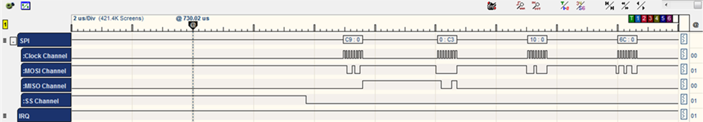
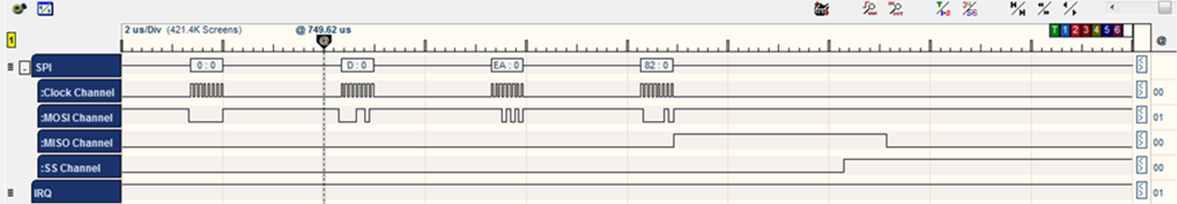
- The WINC acknowledges the command by sending two bytes [C9] [0].
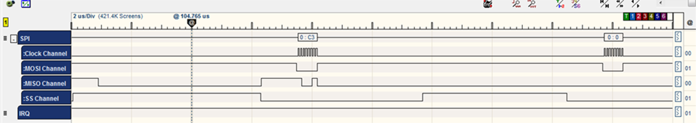
- The HIF layer allows the chip to enter Sleep mode
again.
sint8 hif_chip_sleep(void) { sint8 ret = M2M_SUCCESS; uint32 reg = 0; ret = nm_write_reg(WAKE_REG, SLEEP_VALUE); /* Clear bit 1 */ ret = nm_read_reg_with_ret(0x1, ®); if(reg&0x2) { reg &=~(1 << 1); ret = nm_write_reg(0x1, reg); } }Command CMD_SINGLE_WRITE:0XC9 /* single word write */ BYTE [0] = CMD_SINGLE_WRITE BYTE [1] = address >> 16; /* WAKE_REG address = 0x1074 */ BYTE [2] = address >> 8; BYTE [3] = address; BYTE [4] = u32data >> 24; /* SLEEP_VALUE Data = 0x4321 */ BYTE [5] = u32data >> 16; BYTE [6] = u32data >> 8; BYTE [7] = u32data;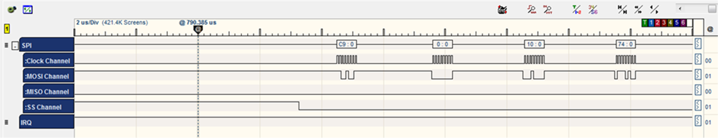
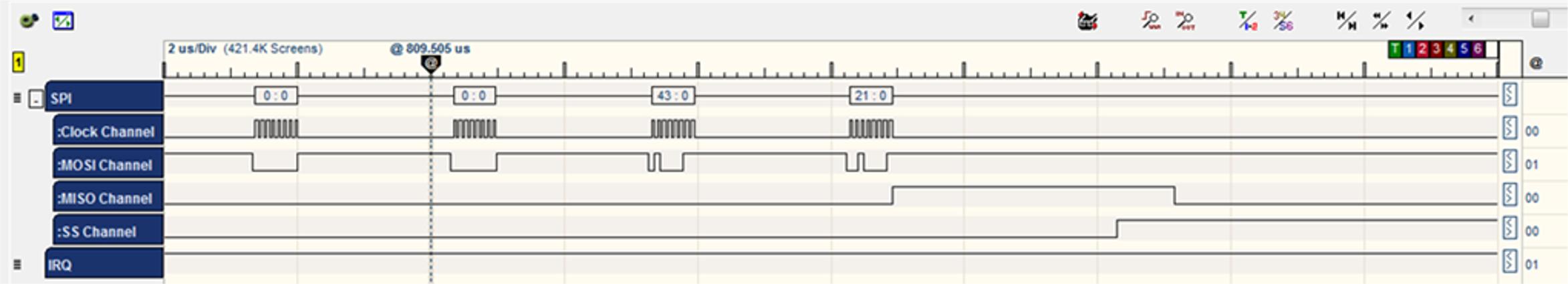
- The WINC acknowledges the command by sending two bytes [C9] [0].

Command        CMD_INTERNAL_READ:	0xC4	/* internal register read */
	        BYTE [0] = CMD_INTERNAL_READ
               BYTE [1] = address >> 8;            /* address = 0x01 */
	        BYTE [1] |= (1 << 7);               /* clockless register */
	        BYTE [2] = address;
	        BYTE [3] = 0x00;
- The WINC acknowledges the command by sending three bytes [C4] [0] [F3].
- The WINC chip sends the value of the register 0x01 which equals 0x03.
Command	CMD_INTERNAL_WRITE:	C3	    /* internal register write	  */
		BYTE [0] = CMD_INTERNAL_WRITE
		BYTE [1] = address >> 8;		/* address = 0x01 	 */
		BYTE [1] |= (1 << 7);                 /* clockless register	 */
		BYTE [2] = address;
		BYTE [3] = u32data >> 24;		/* Data = 0x01 		*/
		BYTE [4] = u32data >> 16;
		BYTE [5] = u32data >> 8;
		BYTE [6] = u32data;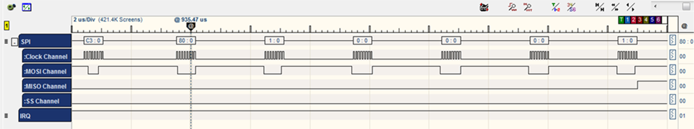
- The WINC chip acknowledges the command by sending two bytes [C3] [0].

- At this point, the HIF layer has completed posting the scan Wi-Fi request to the WINC chip for processing.