
14.3.2 RX (Receive Response)
After finishing the required operation (scan Wi-Fi), the WINC interrupts the host to notify of the processing of the request. The host handles this interrupt to receive the response.
- First step in
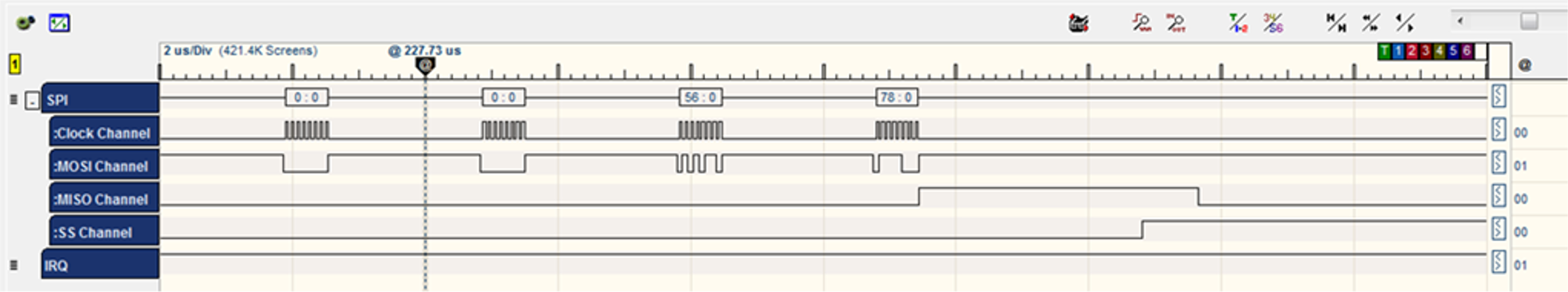
hif_isris to wake up the WINC chip.sint8 nm_clkless_wake(void) { ret = nm_read_reg_with_ret(0x1, ®); /* Set bit 1 */ ret = nm_write_reg(0x1, reg | (1 << 1)); // Check the clock status ret = nm_read_reg_with_ret(clk_status_reg_adr, &clk_status_reg); // Tell Firmware that Host waked up the chip ret = nm_write_reg(WAKE_REG, WAKE_VALUE); return ret; }Command CMD_INTERNAL_READ: 0xC4 /* internal register read */ BYTE [0] = CMD_INTERNAL_READ BYTE [1] = address >> 8; /* address = 0x01 */ BYTE [1] |= (1 << 7); /* clockless register */ BYTE [2] = address; BYTE [3] = 0x00;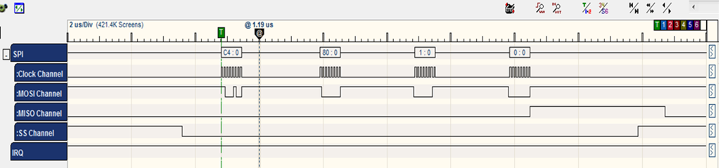
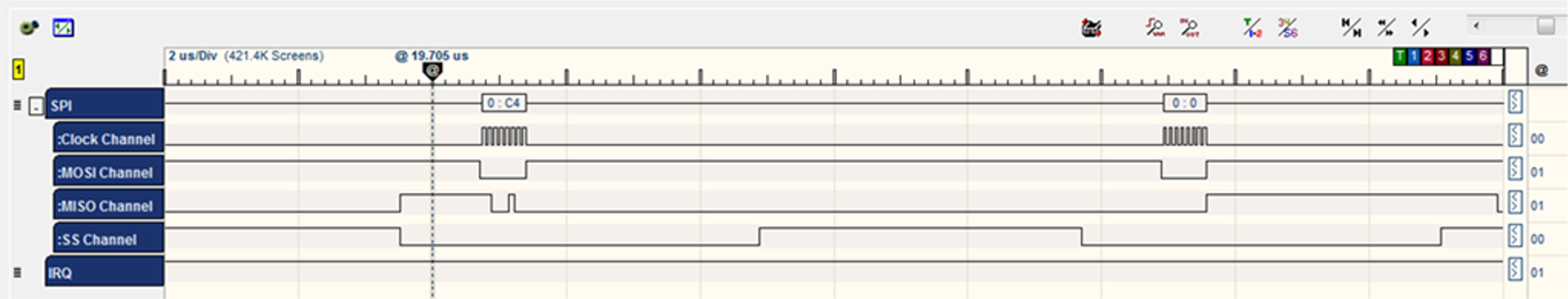
- The WINC acknowledges the command by sending three bytes [C4] [0] [F3].

- The WINC chip sends the value of the register 0x01 which equals 0x01.
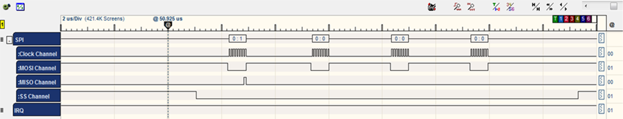
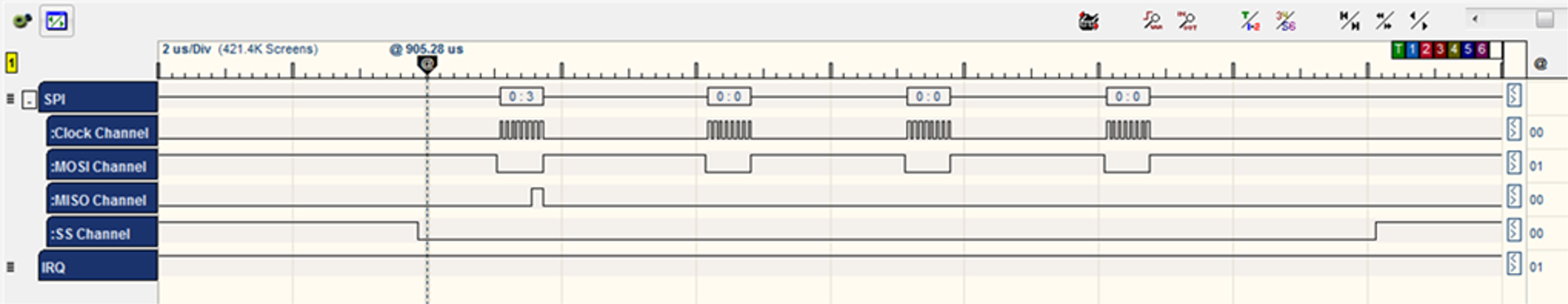
Command CMD_INTERNAL_WRITE: C3 /* internal register write */ BYTE [0] = CMD_INTERNAL_WRITE BYTE [1] = address >> 8; /* address = 0x01 */ BYTE [1] |= (1 << 7); /* clockless register */ BYTE [2] = address; BYTE [3] = u32data >> 24; /* Data = 0x03 */ BYTE [4] = u32data >> 16; BYTE [5] = u32data >> 8; BYTE [6] = u32data;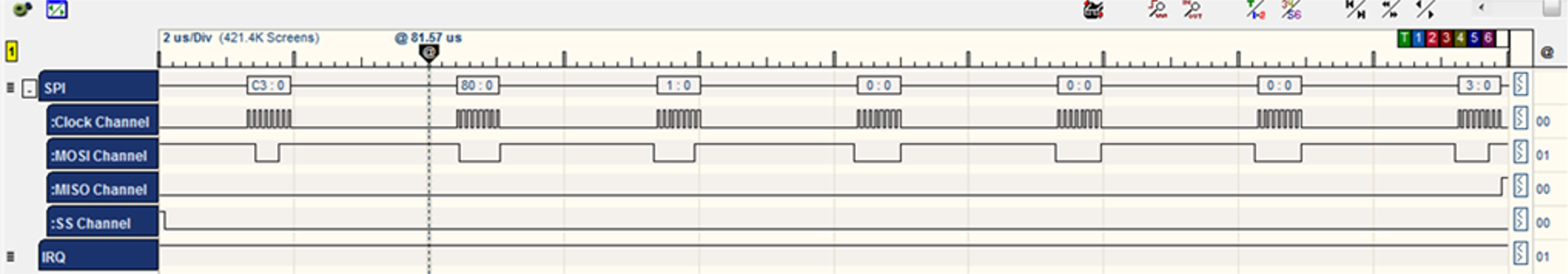
- The WINC acknowledges the command by sending two bytes [C3] [0].
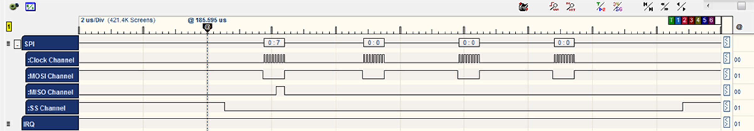
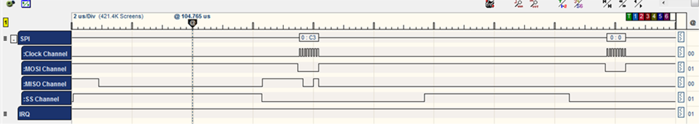
Command CMD_INTERNAL_READ: 0xC4 /* internal register read */ BYTE [0] = CMD_INTERNAL_READ BYTE [1] = address >> 8; /* address = 0x0F */ BYTE [1] |= (1 << 7); /* clockless register */ BYTE [2] = address; BYTE [3] = 0x00;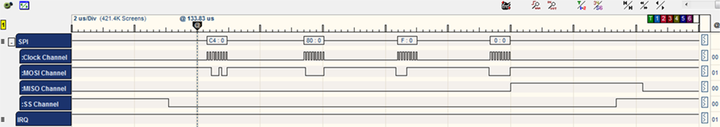
- The WINC acknowledges the command by sending three bytes [C4] [0] [F3].
- Then WINC chip sends the value of the register 0x01 which equals 0x07.
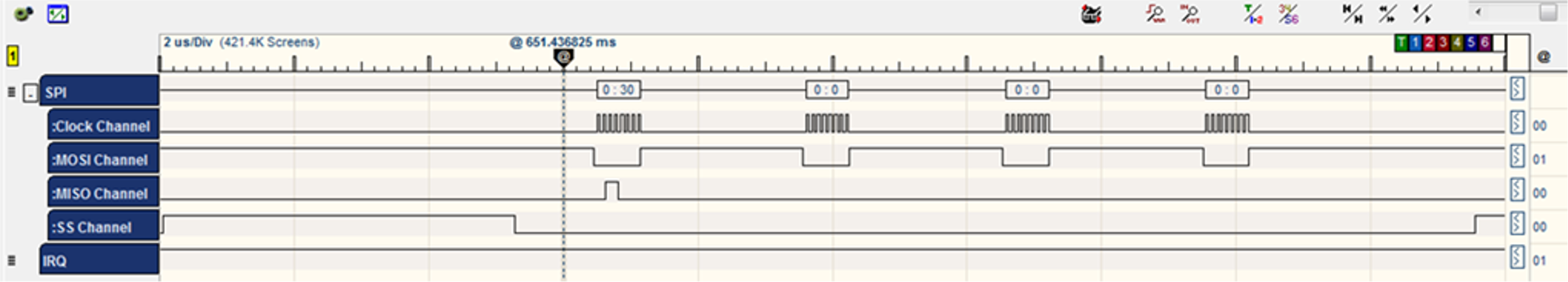
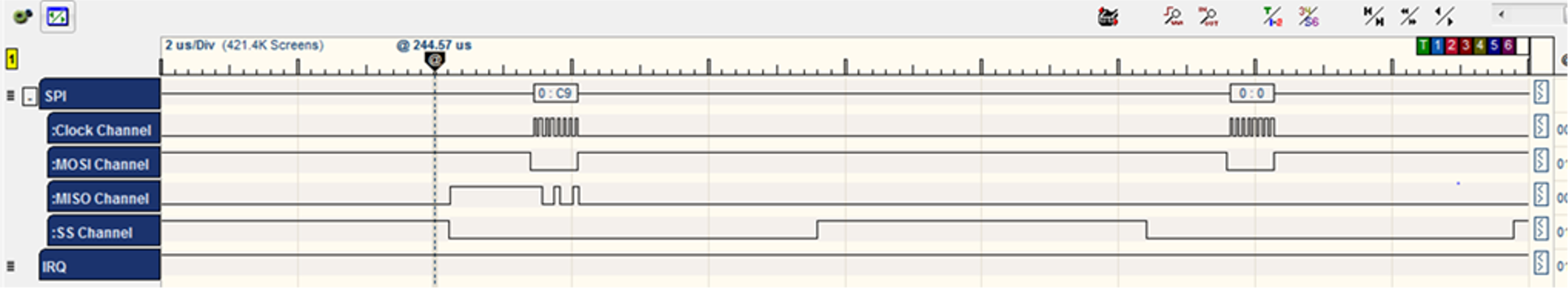
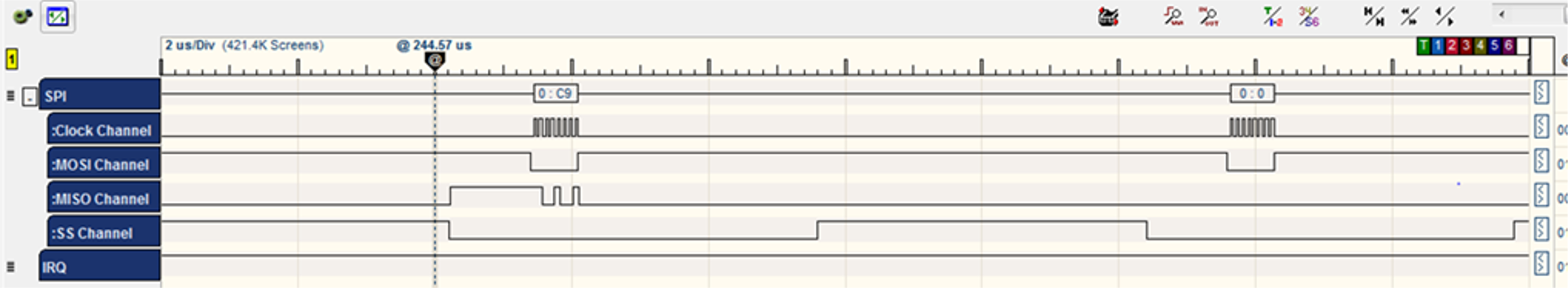
Command CMD_SINGLE_WRITE:0XC9 /* single word write */ BYTE [0] = CMD_SINGLE_WRITE BYTE [1] = address >> 16; /* WAKE_REG address = 0x1074 */ BYTE [2] = address >> 8; BYTE [3] = address; BYTE [4] = u32data >> 24; /* WAKE_VALUE Data = 0x5678 */ BYTE [5] = u32data >> 16; BYTE [6] = u32data >> 8; BYTE [7] = u32data;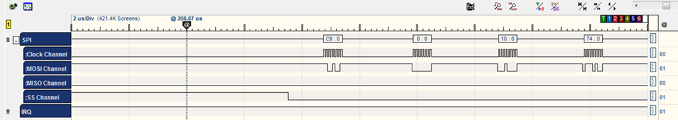
- The chip acknowledges the command by sending two bytes [C9] [0].

- Read register WIFI_HOST_RCV_CTRL_0 to check if there is a new interrupt, and clear
it.
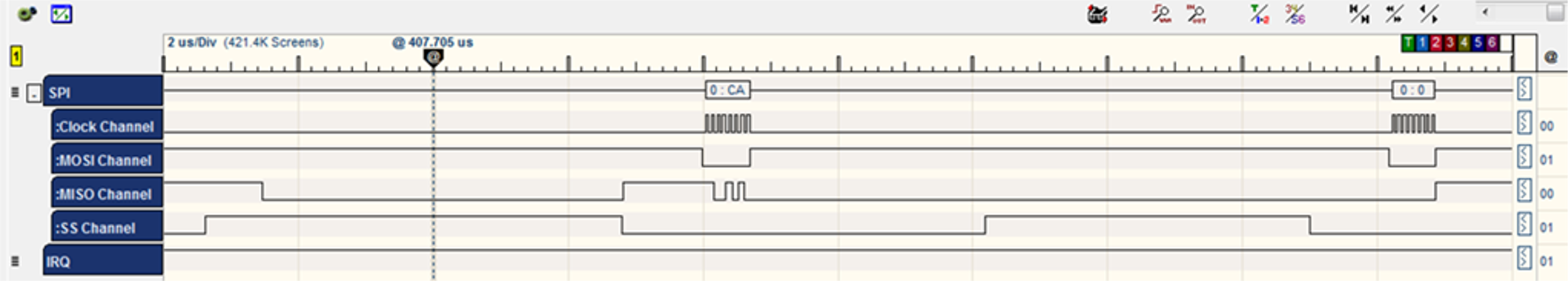
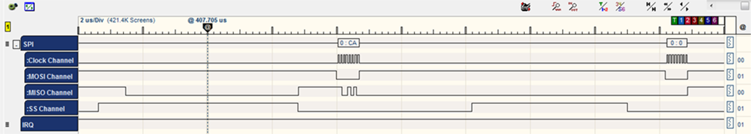
static sint8 hif_isr(void) { sint8 ret ; uint32 reg; volatile tstrHifHdr strHif; ret = hif_chip_wake(); ret = nm_read_reg_with_ret(WIFI_HOST_RCV_CTRL_0, ®); if(reg & 0x1) /* New interrupt has been received */ { uint16 size; /*Clearing RX interrupt*/ ret = nm_read_reg_with_ret(WIFI_HOST_RCV_CTRL_0,®); reg &= ~(1<<0); ret = nm_write_reg(WIFI_HOST_RCV_CTRL_0,reg);Command CMD_SINGLE_READ: 0xCA /* single word (4 bytes) read */ BYTE [0] = CMD_SINGLE_READ BYTE [1] = address >> 16; /* WIFI_HOST_RCV_CTRL_0 address = 0x1070 */ BYTE [2] = address >> 8; BYTE [3] = address;
- The WINC acknowledges the command by sending three bytes [CA] [0] [F3].

- The WINC chip sends the value of the register 0x1070 which equals 0x31.
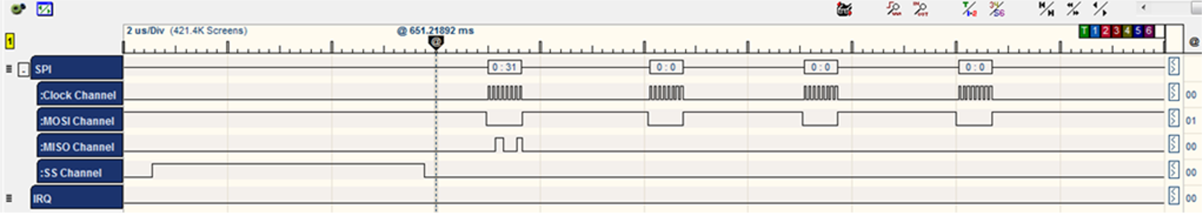
Command CMD_SINGLE_READ: 0xCA /* single word (4 bytes) read */ BYTE [0] = CMD_SINGLE_READ BYTE [1] = address >> 16; /* WIFI_HOST_RCV_CTRL_0 address = 0x1070 */ BYTE [2] = address >> 8; BYTE [3] = address;
- The WINC acknowledges the command by sending three bytes [CA] [0] [F3].

- The WINC chip sends the value of the register 0x1070 which equals 0x31.
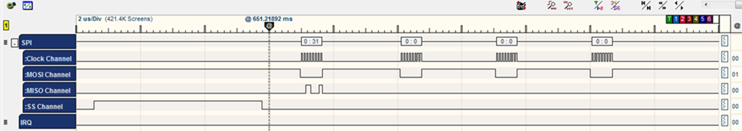
- Clear the WINC
Interrupt.
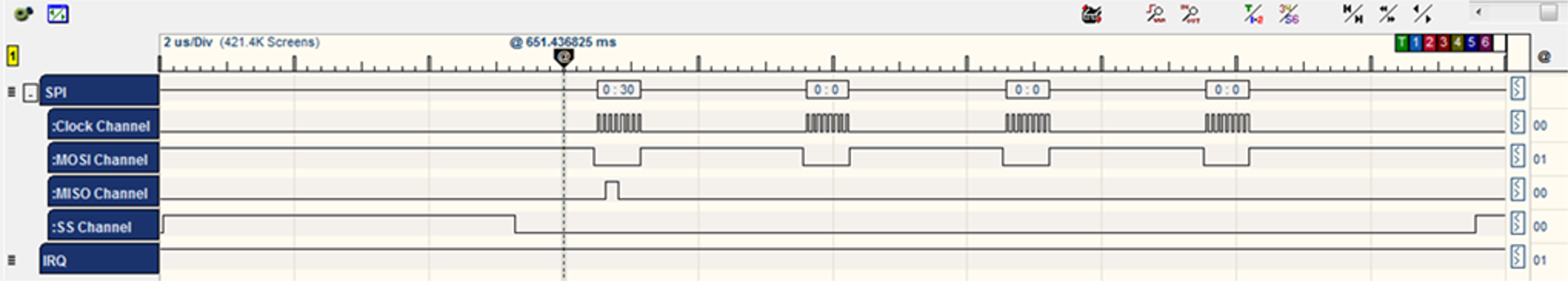
Command CMD_SINGLE_WRITE:0XC9 /* single word write */ BYTE [0] = CMD_SINGLE_WRITE BYTE [1] = address >> 16; /* WIFI_HOST_RCV_CTRL_0 address = 0x1070 */ BYTE [2] = address >> 8; BYTE [3] = address; BYTE [4] = u32data >> 24; /* Data = 0x30 */ BYTE [5] = u32data >> 16; BYTE [6] = u32data >> 8; BYTE [7] = u32data;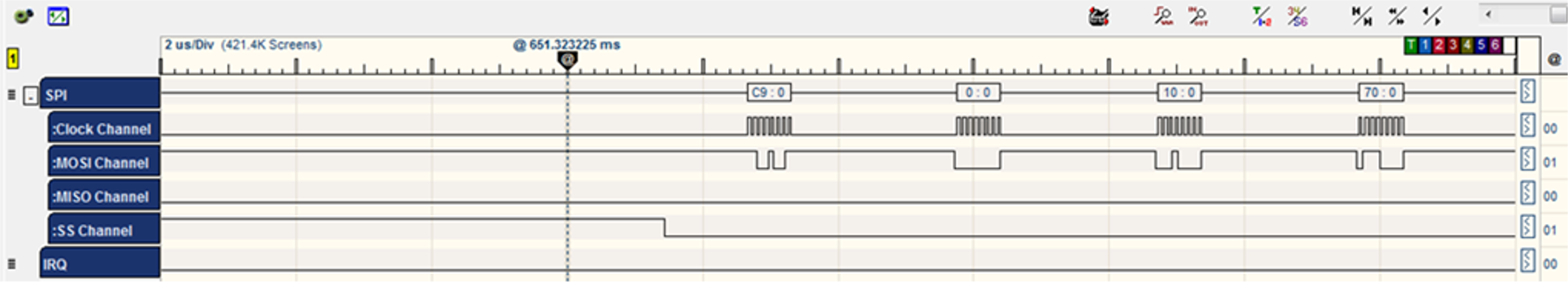
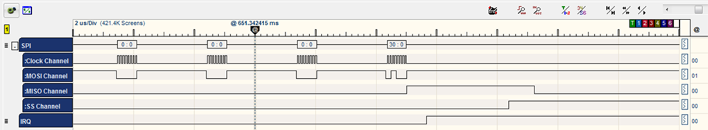
- The chip acknowledges the command by sending two bytes [C9] [0].

- The HIF reads the data
size.
/* read the rx size */ ret = nm_read_reg_with_ret(WIFI_HOST_RCV_CTRL_0, ®);Command CMD_SINGLE_READ: 0xCA /* single word (4 bytes) read */ BYTE [0] = CMD_SINGLE_READ BYTE [1] = address >> 16; /* WIFI_HOST_RCV_CTRL_0 address = 0x1070 */ BYTE [2] = address >> 8; BYTE [3] = address;
- The WINC acknowledges the command by sending three bytes [CA] [0] [F3].
- The WINC chip sends the value of the register 0x1070 which equals 0x30.
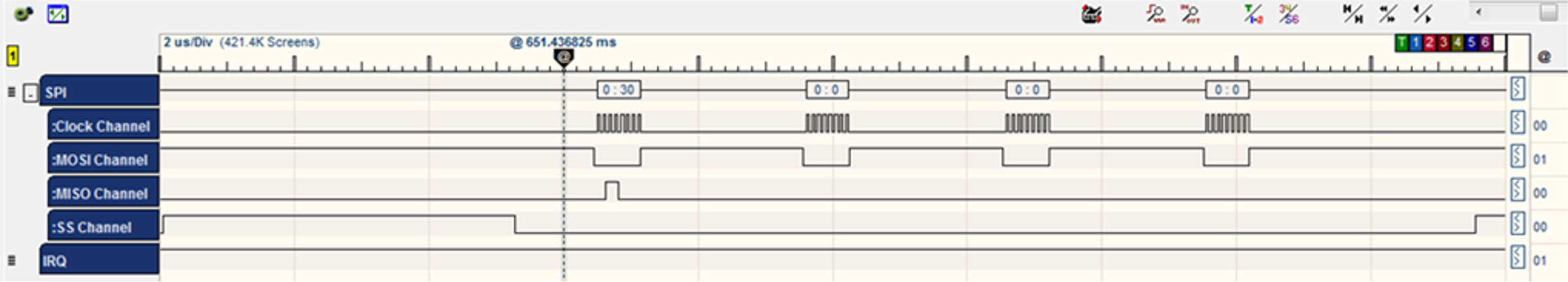
- The HIF reads hif header
address.
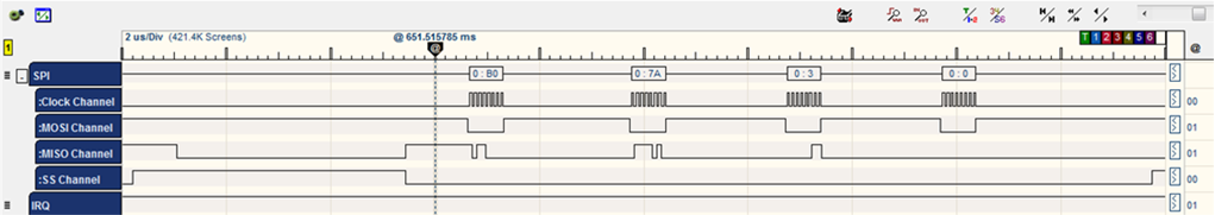
/** start bus transfer**/ ret = nm_read_reg_with_ret(WIFI_HOST_RCV_CTRL_1, &address);Command CMD_SINGLE_READ: 0xCA /* single word (4 bytes) read */ BYTE [0] = CMD_SINGLE_READ BYTE [1] = address >> 16; /* WIFI_HOST_RCV_CTRL_1 address = 0x1084 */ BYTE [2] = address >> 8; BYTE [3] = address;
- The WINC acknowledges the command by sending three bytes [CA] [0] [F3].

- The WINC chip sends the value of the register 0x1078 which equals 0x037AB0.
- The HIF reads the hif header data (as a
block).
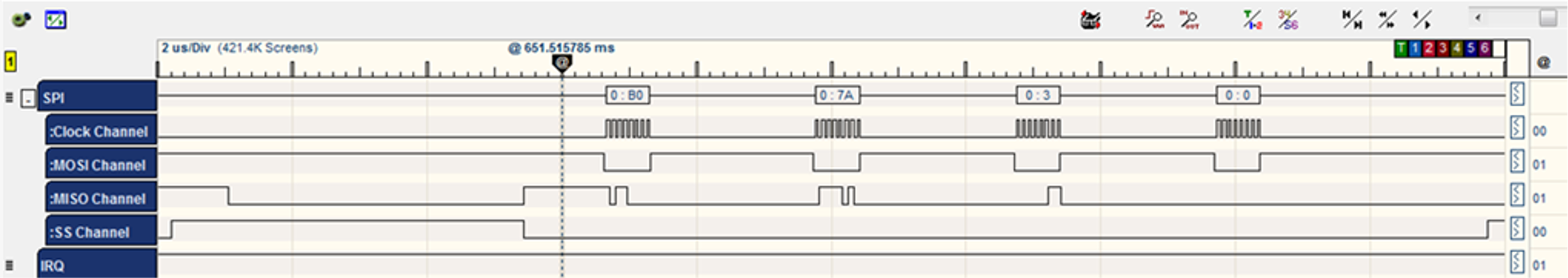
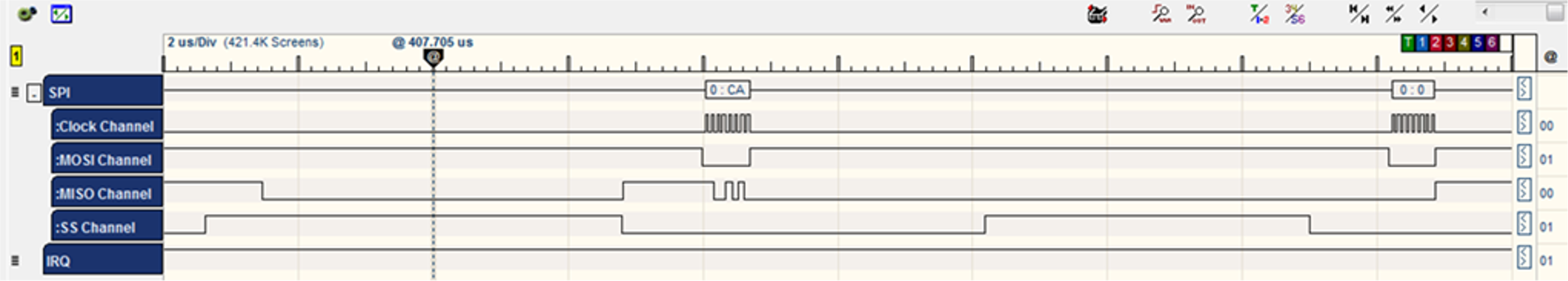
ret = nm_read_block(address, (uint8*)&strHif, sizeof(tstrHifHdr));Command CMD_DMA_EXT_READ: C8 /* dma extended read */ BYTE [0] = CMD_DMA_EXT_READ BYTE [1] = address >> 16; /* address = 0x037AB0*/ BYTE [2] = address >> 8; BYTE [3] = address; BYTE [4] = size >> 16; BYTE [5] = size >>; BYTE [6] = size;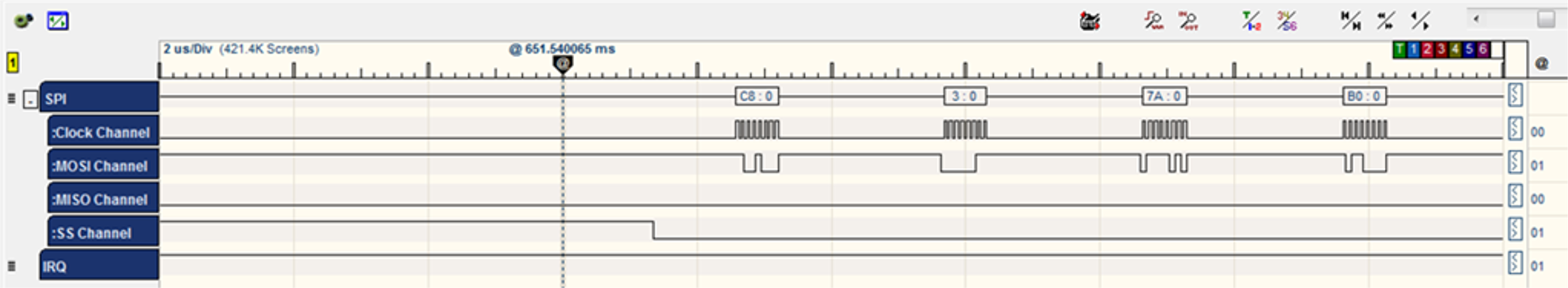
- The WINC acknowledges the command by sending three bytes [C8] [0] [F3].
- The WINC sends the data block (four bytes).
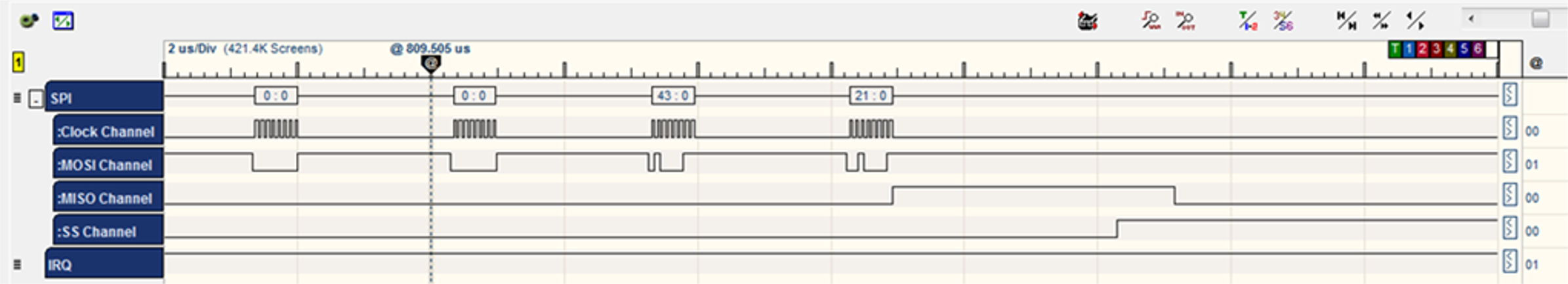
- The HIF calls the appropriate handler
according to the hif header received which tries to receive the Response data
payload.Note:
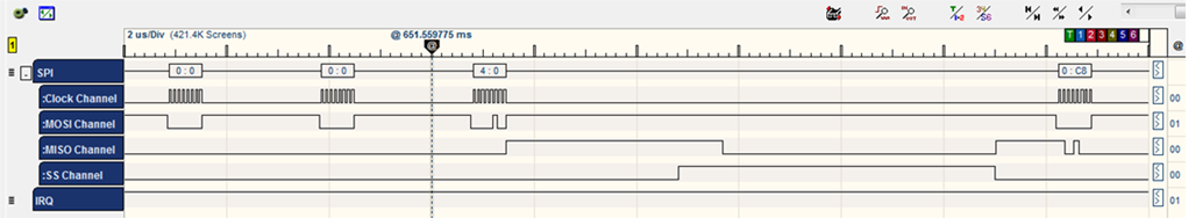
hif_receiveobtains additional data.sint8 hif_receive(uint32 u32Addr, uint8 *pu8Buf, uint16 u16Sz, uint8 isDone) { uint32 address, reg; uint16 size; sint8 ret = M2M_SUCCESS; ret = nm_read_reg_with_ret(WIFI_HOST_RCV_CTRL_0,®); size = (uint16)((reg >> 2) & 0xfff); ret = nm_read_reg_with_ret(WIFI_HOST_RCV_CTRL_1,&address); /* Receive the payload */ ret = nm_read_block(u32Addr, pu8Buf, u16Sz); }Command CMD_SINGLE_READ: 0xCA /* single word (4 bytes) read */ BYTE [0] = CMD_SINGLE_READ BYTE [1] = address >> 16; /* WIFI_HOST_RCV_CTRL_0 address = 0x1070 */ BYTE [2] = address >> 8; BYTE [3] = address;
- The WINC acknowledges the command by sending three bytes [CA] [0] [F3].

- The WINC chip sends the value of the register 0x1070 which equals 0x30.
Command CMD_SINGLE_READ: 0xCA /* single word (4 bytes) read */ BYTE [0] = CMD_SINGLE_READ BYTE [1] = address >> 16; /* WIFI_HOST_RCV_CTRL_1 address = 0x1084 */ BYTE [2] = address >> 8; BYTE [3] = address;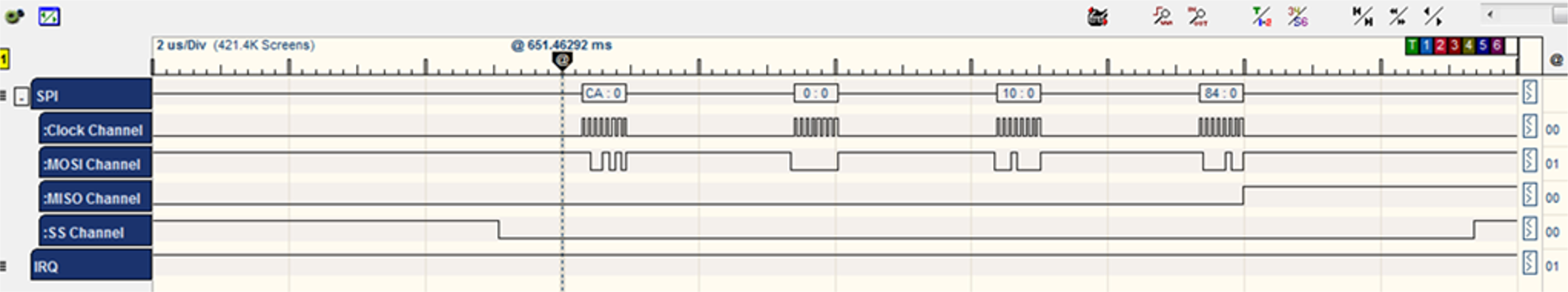
- The WINC acknowledges the command by sending three bytes [CA] [0] [F3].
- The WINC chip sends the value of the register 0x1078 which equals 0x037AB0.
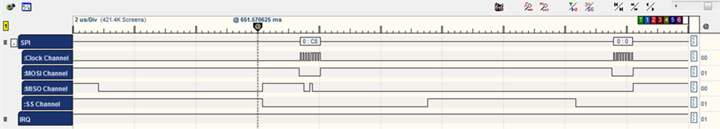
Command CMD_DMA_EXT_READ: C8 /* dma extended read */ BYTE [0] = CMD_DMA_EXT_READ BYTE [1] = address >> 16; /* address = 0x037AB8*/ BYTE [2] = address >> 8; BYTE [3] = address; BYTE [4] = size >> 16; BYTE [5] = size >>; BYTE [6] = size;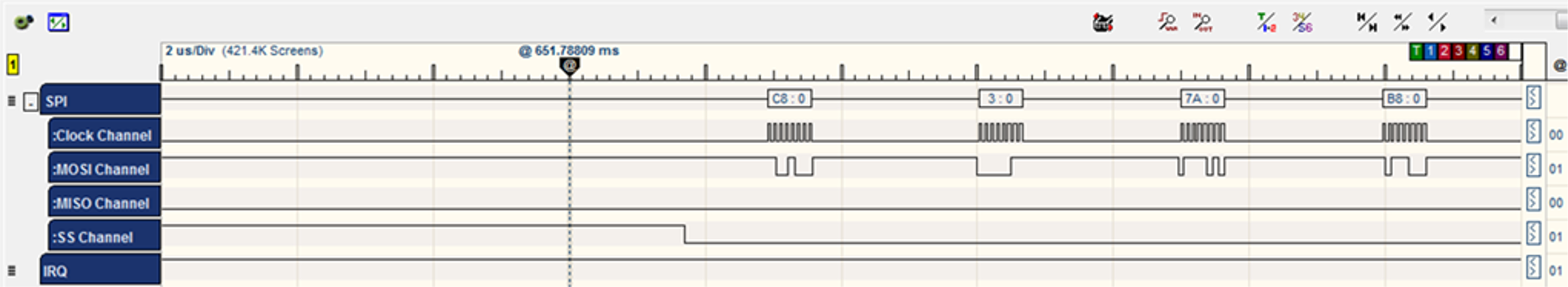

- The WINC acknowledges the command by sending three bytes [C8] [0] [F3].

- The WINC sends the data block (four bytes).
- After the HIF layer received the
response, it interrupts the chip to send the notification that the host RX is
done.
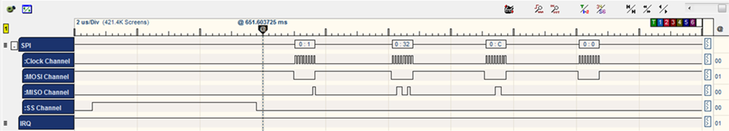
static sint8 hif_set_rx_done(void) { uint32 reg; sint8 ret = M2M_SUCCESS; ret = nm_read_reg_with_ret(WIFI_HOST_RCV_CTRL_0,®); /* Set RX Done */ reg |= (1<<1); ret = nm_write_reg(WIFI_HOST_RCV_CTRL_0,reg); }Command CMD_SINGLE_READ: 0xCA /* single word (4 bytes) read */ BYTE [0] = CMD_SINGLE_READ BYTE [1] = address >> 16; /* WIFI_HOST_RCV_CTRL_0 address = 0x1070 */ BYTE [2] = address >> 8; BYTE [3] = address;
- The WINC acknowledges the command by sending three bytes [CA] [0] [F3].
- The WINC chip sends the value of the register 0x1070 which equals 0x30.
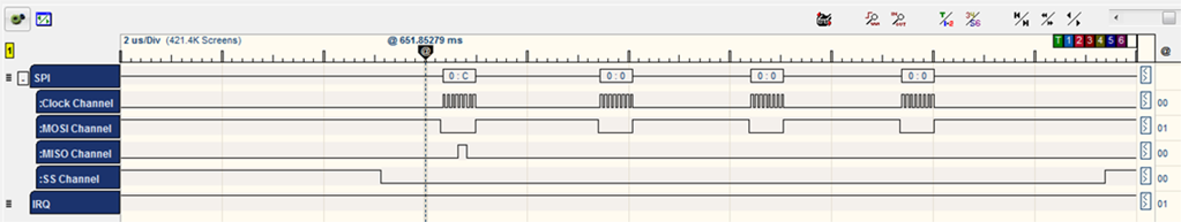
Command CMD_SINGLE_WRITE:0XC9 /* single word write */ BYTE [0] = CMD_SINGLE_WRITE BYTE [1] = address >> 16; /* WIFI_HOST_RCV_CTRL_0 address = 0x1070 */ BYTE [2] = address >> 8; BYTE [3] = address; BYTE [4] = u32data >> 24; /* Data = 0x32*/ BYTE [5] = u32data >> 16; BYTE [6] = u32data >> 8; BYTE [7] = u32data;
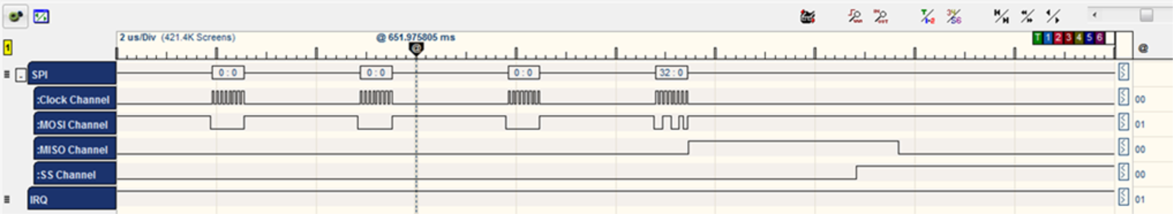
- The chip acknowledges the command by sending two bytes [C9] [0].
- The HIF layer allows the chip to enter Sleep mode
again.
sint8 hif_chip_sleep(void) { sint8 ret = M2M_SUCCESS; uint32 reg = 0; ret = nm_write_reg(WAKE_REG, SLEEP_VALUE); /* Clear bit 1 */ ret = nm_read_reg_with_ret(0x1, ®); if(reg&0x2) { reg &=~(1 << 1); ret = nm_write_reg(0x1, reg); } }Command CMD_SINGLE_WRITE:0XC9 /* single word write */ BYTE [0] = CMD_SINGLE_WRITE BYTE [1] = address >> 16; /* WAKE_REG address = 0x1074 */ BYTE [2] = address >> 8; BYTE [3] = address; BYTE [4] = u32data >> 24; /* SLEEP_VALUE Data = 0x4321 */ BYTE [5] = u32data >> 16; BYTE [6] = u32data >> 8; BYTE [7] = u32data;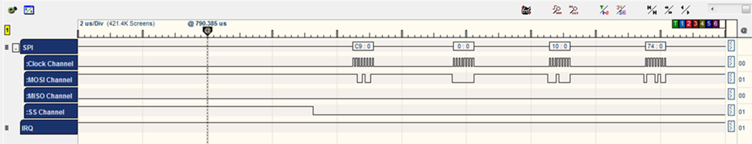
- The WINC acknowledges the command by sending two bytes [C9] [0].
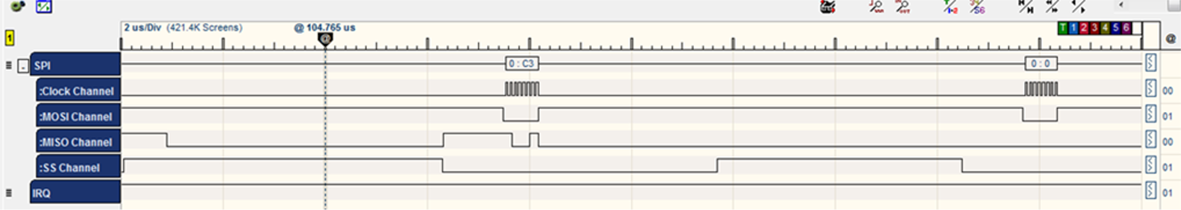
Command CMD_INTERNAL_READ: 0xC4 /* internal register read */ BYTE [0] = CMD_INTERNAL_READ BYTE [1] = address >> 8; /* address = 0x01 */ BYTE [1] |= (1 << 7); /* clockless register */ BYTE [2] = address; BYTE [3] = 0x00; - The WINC acknowledges the command by sending three bytes [C4] [0] [F3].

- Then WINC chip sends the value of the register 0x01 which equals 0x03.
Command	CMD_INTERNAL_WRITE:	C3	 	  /* internal register write	  */
		BYTE [0] = CMD_INTERNAL_WRITE
		BYTE [1] = address >> 8;			/* address = 0x01 	 */
		BYTE [1] |= (1 << 7);			   /* clockless register	 */
		BYTE [2] = address;
		BYTE [3] = u32data >> 24;			/* Data = 0x01 		*/
		BYTE [4] = u32data >> 16;
		BYTE [5] = u32data >> 8;
		BYTE [6] = u32data;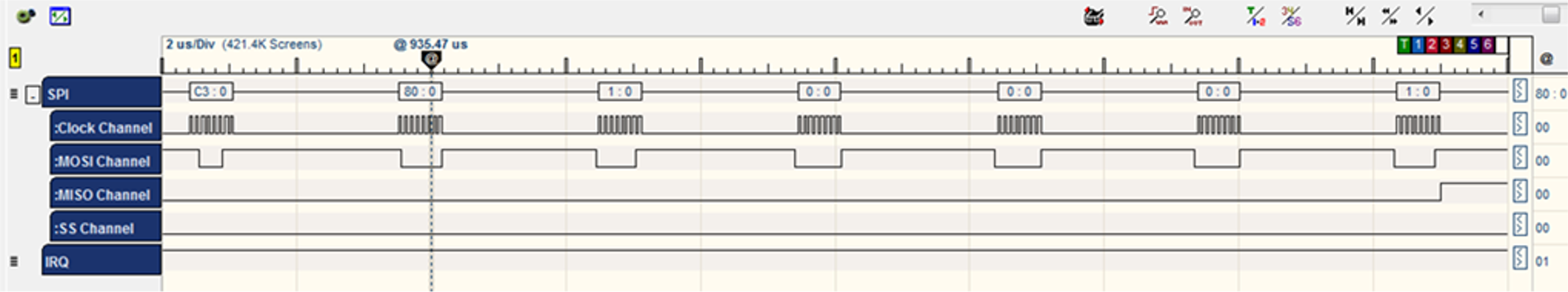
- The WINC chip acknowledges the command by sending two bytes [C3] [0].
- Scan Wi-Fi request is sent to the WINC chip and the response is successfully sent to the host.