The Scope Channels table specifies the variables that are captured by the firmware. In X2Cscope
terms, a single variable is a Channel.
How Buffered Capture Works
Unlike continuous streaming (DVRT), X2Cscope uses a buffered capture approach:
The target MCU samples
selected variables at a fixed rate into a user defined buffer. The buffer is
defined by the user and a pointer to the buffer is passed during
initialization.
When the buffer is full,
sampling stops.
The buffer contents are
transferred to the PC for display.
The process repeats for the
next capture.
This method allows capturing high-frequency signals without requiring high-bandwidth
continuous communication.
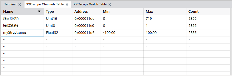
Adding Scope Channels
Select variables using the symbol browser as described in the Selecting Symbolssection. Up to 8
variables may be selected for the scope function. The number of variables and their
sizes (record size) along with the buffer size and the scope configuration determine
the duration of one capture cycle.Figure 8-1. X2Cscope Channels Table Tab
Configuring Scope Sample Time
The Scope Sample Time specifies the period between calls to
X2CScope_Update() in your firmware:
Enter the sample period in
the Scope configuration (e.g. 1 ms for 1 kHz sampling).
Ensure this value matches
your firmware’s actual update rate.
Important:
This setting tells the PC what
rate the firmware is using. It does not change the firmware’s sampling rate.
Sample Time Factor
The Sample Time Factor reduces the effective sampling rate:
A factor of
1 captures every sample.
A factor of
N captures every Nth sample.
For example, with a 1 ms scope sample time and factor of 10, the effective capture
interval is 10 ms. This is useful for:
Capturing slower phenomena
over a longer duration.
Reducing the amount of data
when high time resolution isn't needed.
Extending capture time
without modifying firmware buffer size.
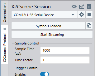
Controlling Data Capture
Figure 8-2. X2Cscope Session
Start and Stop Streaming
Click Start
Streaming to begin continuous capture. The scope repeatedly
fills the buffer, transfers data and displays results.
Click the button again to
stop.
Data capture can run continuously or be controlled by triggers.
Captures repeat automatically, providing updated views of ongoing signals. Single
shot mode is currently not supported by the Data Visualizer.
Capture Duration
The total capture duration depends on several
factors:
Duration = (Buffer Size / Record Size) x Scope Sample Time x Sample Time Factor
Where:
Buffer Size: Determined by
firmware configuration (in bytes).