
4.4.2.1 Hardware Setup
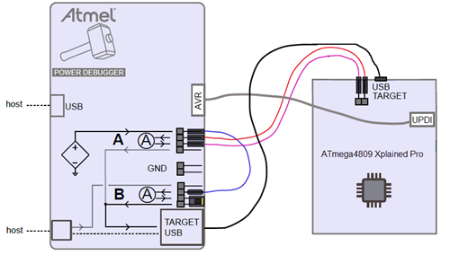
Connect the Power Debugger to the target board according to the block diagram. Connections are described below.
To power the target: the Power Debugger variable voltage supply will be used. This enables testing a USB device over the full voltage range of the USB specification.
To do:
- Connect the variable voltage output to the input of the B channel using a strap cable. This enables measurement of the total current drawn by the target.
- Connect the output of the B channel to the POWER input of the USB type-A jack. This is simply done by using a jumper.
- Connect a USB cable from the type-A jack to the TARGET USB micro-jack.
To measure the current drawn by the target MCU: the Xplained PRO board has a power 2-pin header next to the TARGET USB connector. Usually a jumper is in place here connecting VCC_TARGET to VCC_MCU. By removing this jumper and routing this circuit through a current measurement channel we can measure the current drawn only by the MCU, and not the whole board.
To do:
- Connect VCC_TARGET on the target board to the input of the A channel.
- Connect the output of the A channel to the VCC_MCU pin of the target board.
To program and debug the target device: Although the Xplained PRO has debug capability, we will use the Power Debugger for this purpose.
To do:
• Connect the 10-pin debug cable from the AVR header of the Power Debugger to the UPDI DEBUG header of the Xplained PRO.
To connect all this to the host computer:
To do:
- Connect a USB cable from the DEBUG connector of the Power Debugger to the host computer.
- Connect a USB cable from the TARGET connector of the Power Debugger to the host computer.