
5 Appendix 1: Programming On-board SPI Flash using the Fabric Logic through the Host Loader
(Ask a Question)To program the SPI Flash, perform the following steps:
- Power off the Evaluation board using the SW3 slide switch. Close the PuTTY and set the on-board SW11 (Evaluation board) DIP 1 to ON state.
- Disconnect and connect the USB cable from the host PC to FTDI port J5 on the Evaluation board. This ensures clearing off UART buffers.
- Power on the Evaluation board using the SW3 slide switch.
- Locate the
load_spi_flash.bat batchfile from theDesignFiles_Folder\host_pc_tool_pffolder. Open or edit the
load_spi_flash.batbatch file and ensure that it matches the COM port number. For example, COM Port 9 in this instance.spi_loader.exe 9 golden_image_v0.spi update_image_v2.spi iap_image_v5.spi- Double-click the
load_spi_flash.batfile to load the programming images as listed in the following table—into external SPI Flash. The application firmware writes the Flash directory contents into the external SPI Flash along with programming images.The command window prompts to press Enter to erase and program the SPI Flash with programming images.
The LED 4 blinks to indicate that the SPI Flash Erase operation is in progress. The command prompt displays the status, as shown in the following figure.
Figure 5-1. Erasing SPI Flash 
- The SPI Flash programming operation starts and takes 20–30 minutes to complete. LED 5 blinks to indicate that the SPI Flash programming operation is in progress.
When the SPI Flash programming operation completes successfully, LED 5 starts to glow. The Command prompt shows the status and the time taken, as shown in the following figure.
Figure 5-2. Command Prompt Status 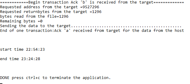
- Close the application.
- Set the on-board SW11 (Evaluation board) DIP1 to OFF state and open the PuTTY terminal. To select the programming options, power cycle the board.