
4 Running the Demo
(Ask a Question)This section describes how to run the authentication, auto update, and IAP. The following procedure assumes that the serial terminal is setup, for more information about setting up the serial terminal, see Serial Terminal Emulation Program Setup.
The on-board 1 GB Micron SPI Flash device is connected to System Controller SPI and can be programmed using the Libero SoC PolarFire software or fabric logic. For more information about programming the on-board SPI Flash using Fabric Logic, see Appendix 1: Programming On-board SPI Flash using the Fabric Logic through the Host Loader.
Before you begin, ensure that the following configurations are in place:
- Ensure that the device is programmed with the
progamming_appnote_only_FPGA_v1.jobfile. See Appendix 2: Programming the Device and External SPI Flash Using FlashPro Express. - Connect the power supply cable to the J9 (Evaluation board) connector on the board.
- Connect the USB cable from the host PC to FTDI port J5 (Evaluation board) on the board.
- Ensure that on-board SW11 (Evaluation board) DIP 1 is set to OFF.
- Open pin 1 and 2 of the J23 jumper.
- Power ON the Evaluation board using the SW3.
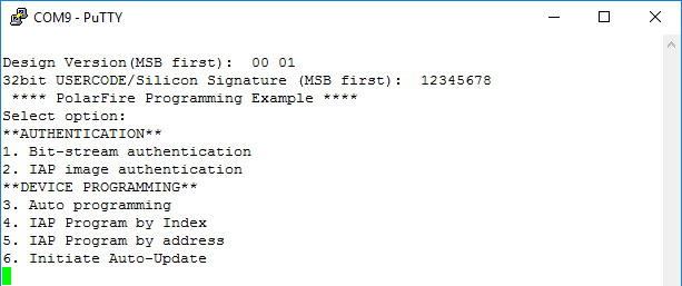
After power-up, PuTTY displays the options as shown in the following figure. Observe the design version 01 loaded onto the device.
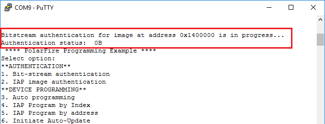
At this point, the on-board SPI Flash device is empty. Hence, selecting Option 1 or 2 returns unsuccessful status codes, as shown in the following figure.
Selecting option 4, 5, or 6 does not initiate any program operation as the on-board SPI Flash is empty.