
5.3.1.6 Low Power Control or Set Power Down
| Firmware Version 1.0 | Firmware Version 1.2 and Later |
|---|---|
SO,<0,1> |
|
Note: All firmware version 1.0 syntax remains valid in version 1.2 and later. | |
Command
SO or SPD enables or disables low-power operation of the RNBD350 module. It expects one single digit as the input parameter.- If the input parameter is ‘
0’, the RNBD350 module runs without low-power operation and UART is active all the time. - If the input parameter is ‘
1’, the RNBD350 module enables Low-Power mode and UART is operational to save power.
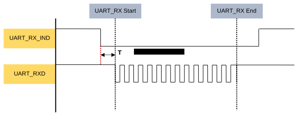
Note: T1 – The time prior to UART data. This time must be greater than 2 ms.
| Item | Firmware Version 1.0 and Later | Description |
|---|---|---|
| Default: | 0 | Low-power mode is disabled |
| Example: | SO,1 | Set RNBD350 to operate under Low-Power mode |
| Response: | AOK | Success |
Err | Syntax error or invalid parameter | |
Note: The parameter of the | ||
| Item | Firmware Version 1.2 and Later | Description |
|---|---|---|
| Default: | 0 | Low-power mode is disabled |
| Example: | SPD,1 | Set RNBD350 to operate under Low-Power mode |
| Response: | AOK | Success |
Err | Syntax error or invalid parameter | |
Note: The parameter of the | ||