Note: For more details, refer to the GPIO Header
(J701 and J702) section of the EV31U42A PIC32-BZ6 Curiosity
Board User's Guide (DS00006006).
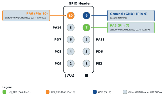
Use the USB-to-UART serial
converter to make the connection between the sample and PC by connecting the
HCI_TXD, HCI_RXD and ground with the converter.
Power the sample with 3.3V
supply.
Select the respective COM
PORT (the COM port with the converter) in MCHPRT3.
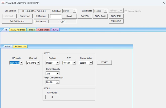
In the RF BT tab, perform
the following steps:
From the “RF mode”
drop-down list, select Test Mode.
Click START to enter the
Bluetooth test mode, then click Disconnect in the GUI. Disconnect the
UART interface from the DUT while keeping the power supply, then connect it with
the Bluetooth tester.
Figure 4-11. MCHPRT3PIC32-BZ6 GUI for Bluetooth Test Mode
Connecting with Bluetooth Tester Demonstration
DS50004106B
The online versions of the documents are provided as a courtesy. Verify all content and data in the device’s PDF documentation found on the device product page.

 Note: For more details, refer to the GPIO Header (J701 and J702) section of the EV31U42A PIC32-BZ6 Curiosity Board User's Guide (DS00006006).