1.5 Considerations For High Speed Transmissions

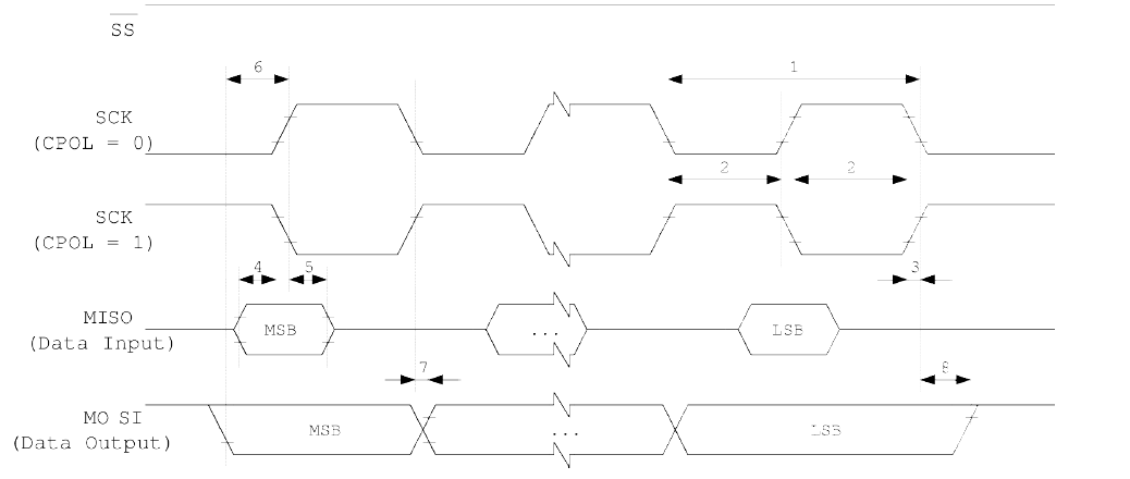
The minimum timing of the clock signal is given by the times “1” and “2”. The value “1” specifies the SCK period while the value “2” specifies the high / low times of the clock signal. The maximum rise and fall time of the SCK signal is specified by the time “3”. These are the first timings of the AVR to check if they match the requirements of the slave.
The Setup time “4” and Hold time “5” are important times because they specify the requirements the AVR has on the interface of the slave. These times determine how long before the clock edge the slave has to have valid output data ready and how long after the clock edge this data has to be valid.
The time “6” (Out to SCK) specifies the minimum time the AVR has valid output data ready before the clock edge occurs. This time can be compared to the Setup time “4” of the slave.

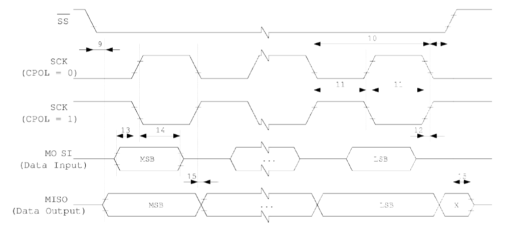
In principle, the timings are the same in slave mode like previously described in master mode. Because of the switching of the roles between master and slave the requirements on the timing are inverted as well. The minimum times of the master mode are now maximum times and vice versa.
