5.5 Setting Output Voltage
The MIC26400 requires two resistors to set the output voltage as shown in Figure 5-4.
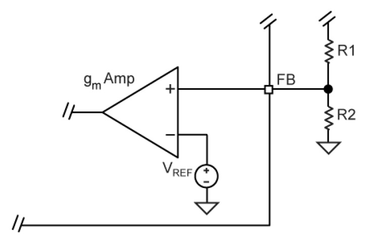
The output voltage is determined by the following equation:
Where:
VFB = 0.8V
A typical value of R1 can be between 3kΩ and 10kΩ. If R1 is too large, it may allow noise to be introduced into the voltage feedback loop. If R1 is too small in value, it will decrease the efficiency of the power supply, especially at light loads. Once R1 is selected, R2 can be calculated using:
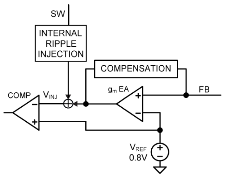
In addition to the external ripple injection added at the FB pin, internal ripple injection is added at the inverting input of the comparator inside the MIC26400, as shown in Figure 5-5. The inverting input voltage VINJ is clamped to 1.2V. As VOUT is increased, the swing of VINJ will be clamped. The clamped VINJ reduces the line regulation because it is reflected back as a DC error on the FB terminal. Therefore, the maximum output voltage of the MIC26400 should be limited to 5.5V to avoid this line regulation problem.