
6.2.4.1 Building and Running the OTA Demo Application
Building the Application
To build this application, open the project file (
apps/ota_demo/firmware/ota_demo_sam_e54_xpro_rnwf02.X ) in MPLAB X IDE.
For more details on opening the project file in MPLAB X IDE, refer to the Opening the
Project file. The following table provides details on the project
file.| Project Name | Description |
|---|---|
ota_demo_sam_e54_xpro_rnwf02.X |
|
Running the Application
- Mount the Serial Flash and
RNWF02 Add On Board on the mikroBUS Xplained pro extension boards. Connect
the RNWF02 connected mikroBUS Xplained pro extension board to the EXTENSION
1 HEADER and Serial Flash connected extension board to EXTENSION 2 HEADER of
SAM E54 Xplained Pro evaluation kit as illustrated in the following
figure.
Figure 6-73. Host Companion Mode 
- Connect the debugger USB port on the SAM E54 Xplained Pro evaluation kit to computer using a micro USB cable.
- Open the project and launch MCC (Microchip Code Configurator).
- Configure Home-AP credentials
for STA mode, using the Wi-Fi settings configuration. For more details about
the Wi-Fi settings configuration, see Figure 3-69.Note: Configure chip-select (CE) for SPI Flash as illustrated in pin settings as shown below.
Figure 6-74. SST26_CE 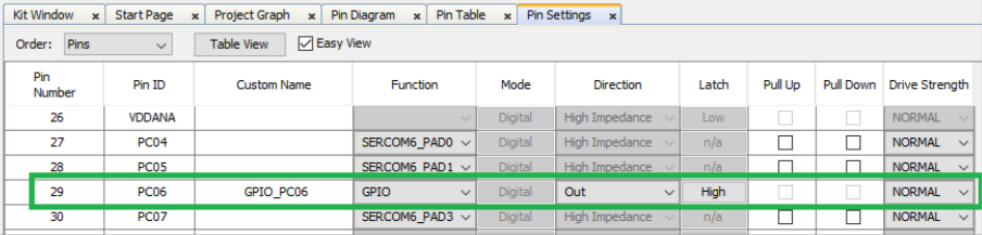
- The following figure
illustrates generate the code procedure.
Figure 6-75. Generating the Code 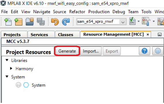
- Build and program the code to
the hardware using MPLAB X IDE.
Figure 6-76. Programming the Board 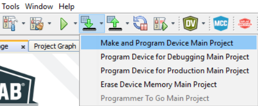
- Open the Terminal application (for example, Tera Term or PuTTY) on the PC
- Connect to the host board
"EDBG Virtual COM Port" and configure the serial settings as follows:
- Baud: 115200
- Data: 8 Bits
- Parity: None
- Stop: 1 Bit
- Flow Control: None
- Press the Reset button on the host board, see Figure 6-58.
- The board boots up and
connects to Home-AP, as per the configurations given in step 4. After the
successful Wi-Fi connection the device opens up a TCP tunnel and wait for
the OTA server and firmware image details from the configurator tool.
Figure 6-77. Initial Firmware Version, OTA Enable 
- Two example sample firmware
binaries are available in the
./ota_demo/toolsfolder, start a python HTTP server using the following command.- From File explorer,
navigate to the folder (
./ota_demo/tools).Figure 6-78. Tools Folder 
- In the address bar,
type cmd and press enter.
Figure 6-79. CMD 
- This will open up a
terminal window, located in this folder.
Figure 6-80. Terminal Window 
- Start an HTTP server,
enter
python -m http.server. By default it will be listening on port 8000.Figure 6-81. Python -m http.server
- From File explorer,
navigate to the folder (
- Run the python OTA
configurator tool from the
./ota_demo/toolsfolder, as illustrated in the following figure.- From File explorer,
navigate to the folder (
./ota_demo/tools).Figure 6-82. Tools Folder - In the address bar,
type cmd and press Enter.
Figure 6-83. CMD - This will open up a
terminal window, located in this folder.
Figure 6-84. Terminal Window - Run the python OTA
configurator by typing
python mchp_configurator.py. Follow the instructions on the terminal, enter http server IP, port and file-name image you want the RNWF to download.Note: Press Enter when requested to enter IP and port and it will default to the computer IP and port 8000.Figure 6-85. OTA Configurator 
- From File explorer,
navigate to the folder (
- Now the device creates a HTTP
link with the OTA server and starts downloading the image file.
Figure 6-86. Image Download 
- After successfully
downloading the image, the DFU is triggered and firmware is Flashed into the
RNWF02 module.
Figure 6-87. DFU Progress 
- Upon successful DFU, the host
will Reset and print the RNWF02 module’s new
firmware information.
Figure 6-88. Updated Firmware 
Note: In the provided OTA demo example, the device’s firmware revision (v3.0.0) matches the
firmware version on the OTA server (v3.0.0). However, in future firmware releases, the
device’s firmware revision will update to the latest version after an OTA update (for
example, from v3.0.0 to v4.0.0).