24.2.1 Half-Bridge Mode
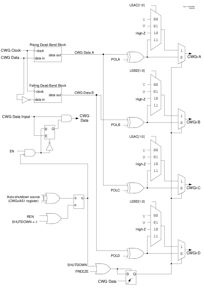
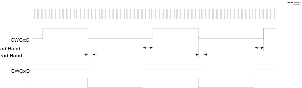
In Half-Bridge mode, two output signals are generated as true and inverted versions of the input, as illustrated in Figure 24-1. A nonoverlap (dead-band) time is inserted between the two outputs to prevent shoot-through current in various power supply applications. Dead-band control is described in 24.7 Dead-Band Control. The output steering feature cannot be used in this mode. A basic block diagram of this mode is shown in Figure 24-2.
The unused outputs CWGxC and CWGxD drive similar signals, with polarity independently controlled by the POLC and POLD bits, respectively.
Note: CWGx_rising_src = CCP1_out,
CWGx_falling_src = ~CCP1_out
100)