
9.2.1.3 Project Generation with Thread CoAP MCC Component
For more details, refer to the Getting Started from Related Links.
Introduction
Thread CoAP example solution application projects are available for reference at <Discover Path>wireless_apps_pic32cxbz3_wbz35\apps\thread\advanced_applications\CoAP. These projects can be generated by following the step-by-step procedure outlined in this document.
Recommended Reading
- For more details on getting started with thread, refer to the Microchip Thread SDK in the Additional Resources of Reference Documentation from Related Links.
Hardware Requirement
- WBZ351 Curiosity Board
- Micro USB Cables
- PC
Software Requirement
For more details, refer to the Microchip Thread SDK in the Additional Resources section of Reference Documentation from Related Links.
Additionally, it depends on version v1.8.1 of the MCC package wireless_system_pic32cxbz_wbz.
Generating Project
This section explains the steps required to develop this application example from scratch using MPLABx Code Configurator.
Note: The recommendation for the new users of the MPLAB Code
Configurator is to refer MPLAB® Code Configurator (MCC) User’s Guide in Reference
Documentation from Related Links.
- Create a new MCC Harmony Project. For more details, refer to the Creating a New MCC Harmony Project from Related Links.
- On the MPLAB X IDE toolbar, look for the
icon labeled MCC. Click on the MCC icon to launch the MPLAB Code
Configurator.
Figure 9-7. MPLAB Toolbar – MCC 
- The following figure illustrates the
opening window of the MPLAB Code Configurator.
Figure 9-8. MPLAB Code Configurator Window 
- The following figure illustrates the
opening window of the MPLAB Code Configurator.
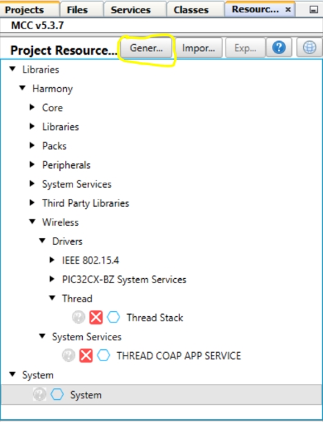
- To add “THREAD COAP APP SERVICE”
component, perform the following steps:
- On the left panel, locate the Device Resources tab.
- Click the arrow next to “Wireless” to expand the category.
- Under “Wireless”, expand “System Services”.
- Click the plus (+) (green) symbol next to THREAD COAP APP SERVICE.
- This action adds the component to the project’s Project Graph.
- Upon Thread CoAP Component being added to
project graph, the different component dependencies will be requested to be added. The
user has to select Yes to add all the dependent components.
Figure 9-9. Components Auto-Activation Confirmation 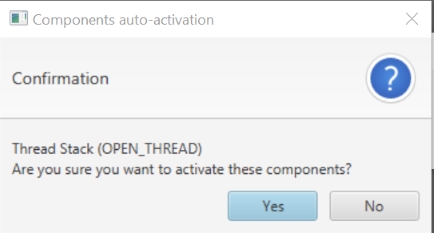
- Users are expected to click Yes for all dependent components.
- Right click on TIME module for selecting
the timer source, Select any of the timer.
Figure 9-10. Selecting Timer Source 
- The following figure illustrates the
component project graph.
Figure 9-11. Thread COAP Component Project Graph 
- Click on the ‘THREAD COAP APP
SERVICE‘, then use the configuration menu to set up the component according to user
needs. Follow the steps outlined in the Thread CoAP Component Configuration
section.
Figure 9-12. Thread CoAP Component Configuration 
- This step is applicable only if the
device is enabled as a sleep end device. Select the clock configurations from the plugins
and make the following clock configuration changes. The following figure illustrates the
clock configuration changes.
Figure 9-13. Clock Configuration Changes 
- Add a console component to facilitate
application console prints. Users can trigger the console by clicking on the
CONSOLE component. The component is a part of System Services.
Figure 9-14. Adding CONSOLE Component 
- Right Click on instance0 UART
for selecting the UART source, Select SERCOM0.
Figure 9-15. Selecting SERCOM0 (sercom0) Satisfiers 
- Right Click on instance0 UART
for selecting the UART source, Select SERCOM0.
- In the Project Graph, find and click on
SERCOM 0 and perform the following steps:
- In the Configuration Options tab, locate and change the “Receive Pinout” and “Transmit Pinout” settings.
- Click Save or Generate to update the MCC configuration files.
Figure 9-16. Change Receive Pinout 
- Perform the following to configure the
“SERCOM0” to enable the Direct High Speed.
- In Project Graph, click the System component to open Configuration Options tab.
- To locate “SERCOM0 Direct (High Speed) Pin Enable (SCOM0_HSEN)”, navigate to System>Device & Project Configuration>WBZ351 Device Configuration>Generate Fuse Settings>DEVCFG1
- From the “SERCOM0 Direct (High Speed) Pin Enable (SCOM0_HSEN” drop-down list, select DIRECT.
Figure 9-17. SERCOM0 Direct (High Speed) Pin Enable (SCOMO_HSEN) 
- Click on Generate Tab for Code
generation. Upon code generation, Thread CoAP Component related source files will be added
to the project. For more details on code generation, refer to the MPLAB Code
Configurator (MCC) Code Generation from Related Links.
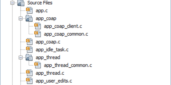
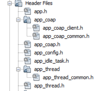
- Once Generation completes the header,
source files of Thread CoAP service will be added under Header and Source Files based on
the configuration.
- app_user_edits.c file changes: selected
line should be commented by following edit step description.
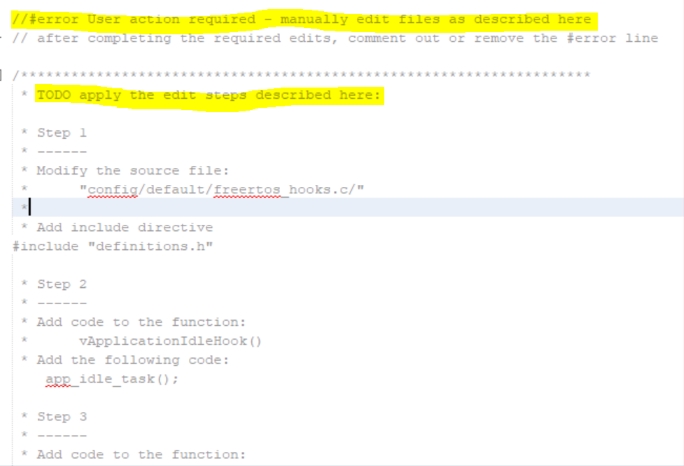
- app_user_edits.c file changes: selected
line should be commented by following edit step description. For more details, refer to
the User Action from Related Links.
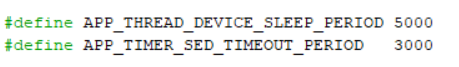
- According to user needs, the user can
modify the Thread network parameters configuration by altering the macros in the file
app_thread/app_thread_common.h. Additionally, the user can adjust
the Thread sleep period and active period by changing the macro values in the file
app_thread.h for
APP_THREAD_DEVICE_SLEEP_PERIODandAPP_TIMER_SED_TIMEOUT_PERIOD, if sleep is enabled. Also user can adjust data polling period by changing the macro values in the file src\config\default\driver\thread\inc\openthread_stack_config.h forOPENTHREAD_CONFIG_MAC_ATTACH_DATA_POLL_PERIOD. Change the value to 100 for higher response if sleep is enabled.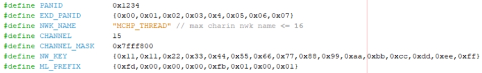
- Switch to MPLAB X IDE window and Build
Project. The project must compile successfully.
