2.2 Assembling the Atmel JTAGICE3
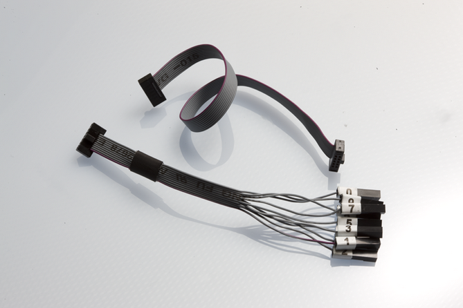
The Atmel JTAGICE3 unit is shipped with no cables attached. Two cable options are provided in the accessory kit:
-
50-mil 10-pin IDC flat cable
-
50-mil 10-pin mini-squid cable with 10 x 100-mil sockets

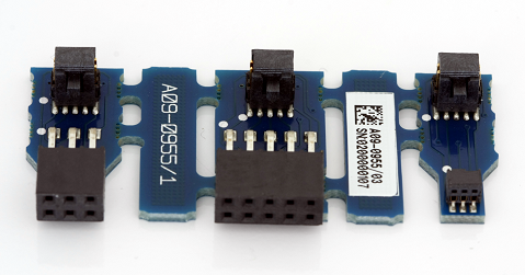
For most purposes, the 50-mil 10-pin IDC flat cable can be used along with one of the adapters provided in the accessory kit. Three adapters are provided in one small PCB panel section. To separate the adapters, simply break off each one by gently bending the panel backwards and forwards. Take care to avoid any sharp edges, which may result from the separation process. The following adapters are included:
-
A09-0955 - A 100-mil 10-pin JTAG adapter
-
A09-0955 - B 100-mil 6-pin SPI/debugWIRE/PDI/aWire adapter
-
A09-0955 - C 50-mil 6-pin SPI/debugWIRE/PDI/aWire adapter

Note that a 50-mil JTAG adapter has not been provided - this is because the 50-mil 10-pin IDC cable can be used to connect directly to a 50-mil JTAG header. For the part number of the component used for the 50-mil 10-pin connector, see target connectors part numbers.
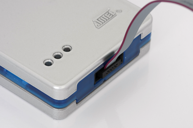
To assemble your JTAGICE3 into its 'default' configuration, connect the 10-pin 50-mil IDC cable to the unit as shown below. Be sure to orient the cable so that the red wire (pin 1) on the cable aligns with the triangular indicator on the blue belt of the enclosure. The cable should connect upwards from the unit.

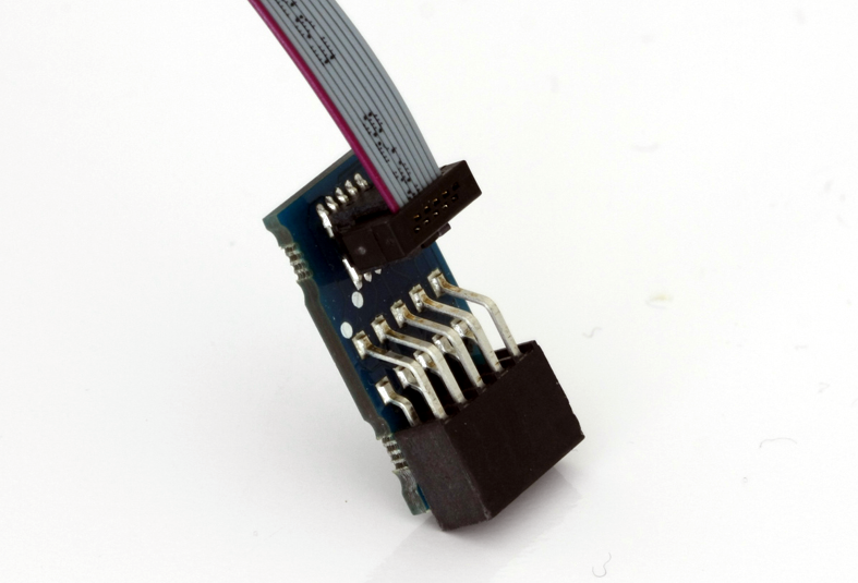
Next, snap off the 100-mil 10-pin JTAG adapter from the adapter panel, and connect it to the other side of the IDC cable. Your Atmel JTAGICE3 is now ready to use in its basic JTAG configuration.

