8.2.2 Serial Peripheral Interface Board
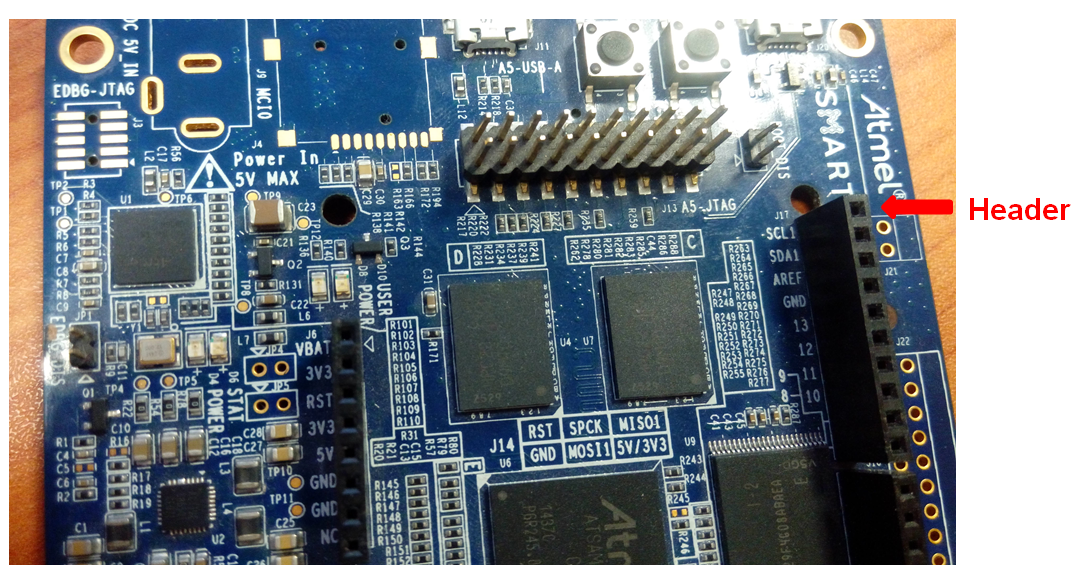
The ATWILC1000 Serial Peripheral Interface (SPI) Board must be connected to the SPI1 interface at J17 as shown in the following figure.

| SPI Pins | Header J17 Pins | XPRO EXT1 Pins |
|---|---|---|
| MOSI | PIN11 | PIN16 |
| CLK | PIN13 | PIN18 (SPCK) |
| MISO | PIN12 | PIN17 |
| CS | PIN10 | PIN15 |
| IRQ | PIN8 | PIN9 |
Note: VEXT pin in the SPI card can be
connected to the 3V3 pin in the header J6. Alternatively, the WINC1500/WINC3400 Xplained
Pro boards can be directly connected to the XPRO EXT1 header, which exposes the same
SPI1 peripheral exposed on J17. In this case, the IRQ GPIO has to be changed to PB26,
which is pin9 of XPRO EXT1.
Use the following commands to load the ATWILC1000 module SPI
driver.
# insmode wilc-spi
Registering wifi device
Max scan ids= 10,Max scan IE len= 1000,Signal Type= 1,Interface Modes= 844
Initializing Locks ...
WILC_SPI spi1.0: WILC SPI probe success