6.1 Programming the ATA5702 on the ATAB5702A Fob
Board
To program the ATA5702 on the ATAB5702A fob board, first connect the programmer (for example,
Atmel-ICE or JTAGICE3) to the ISP header located near the center of the board. The
following steps use an Atmel-ICE programmer and the ISP interface for programming:
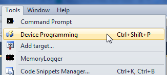
In Microchip Studio 7, navigate
to Tools > Device Programming.Figure 6-1. Device
Programming
Select the Tool, Device and
Interface, as shown in the following figure, then click Apply.Figure 6-2. ATA5702 Device
Selection
Ensure that the ISP frequency is
less than 100 kHz. Click Set.Figure 6-3. ATA5702 ISP Clock
Frequency
Click the Read button to
ensure that the signature matches the selected device.Figure 6-4. ATA5702 Signature
Verification
Select the Fuses tab, then
verify that the proper fuse settings exist. If not, change them to match the
following figure, then click the Program button.Figure 6-5. ATA5702 Fuse
Settings
Select the Memories tab,
then click the Erase now button.
Browse to locate the
ATAB5702A-V2.3B_flash.hex file for the flash memory
image.
Click the Program button,
then wait for completion.
Browse to locate the
ATA5702_eeprom.eep file for the EEPROM memory image.
Click the Program button,
then wait for completion.
Figure 6-6. ATA5702 Memory Settings
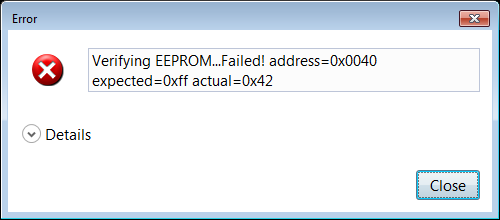
Note: If the EEPROM verification fails
(as shown in the following figure), repeat steps 1-10 to ensure the configuration is
correct. If the error still occurs, then the ATA5702 IC version is outdated and the
user must contact their local sales representative for an upgrade.
Figure 6-7. EEPROM Verification Failure
The online versions of the documents are provided as a courtesy. Verify all content and data in the device’s PDF documentation found on the device product page.