2.2 I/O Pins
These components are used to enable the I/O operations that the bootloader implements
during execution.
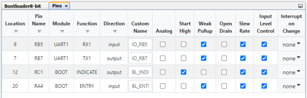
Entry Pin: The Input Pin (Entry Pin) is generally used to control a push button or similar peripheral on the board that forces the bootloader into a ‘boot-ready’ state, this is normally done through an electrical signal that is sent to the MCU from the port that the Entry Pin is connected to. Many times this functionality will be used during development but it is usually not the best solution for the field. The systems needs to be built to be able to move back and forth from the bootloader to the application without the user needing to force an entry.
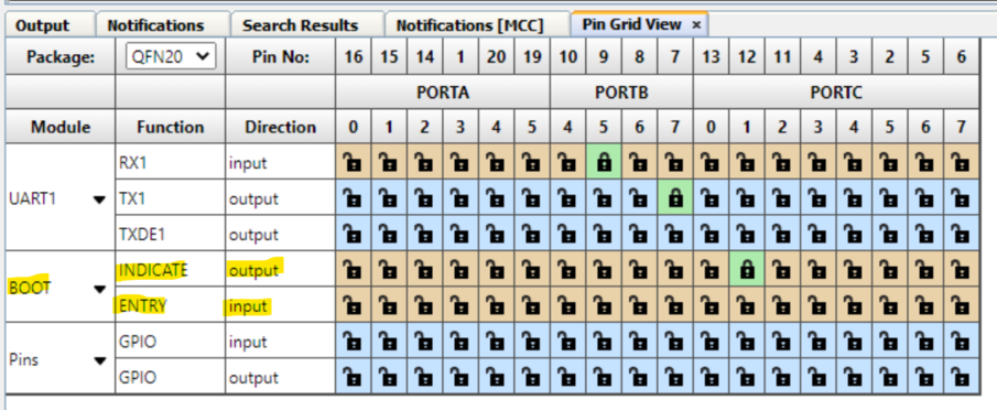
Indicator Pin: The Output Pin (Indicator Pin) is used to tell the user of the bootloader what state the bootloader is currently in by blinking or not blinking an on-board LED. The Pin Grid View gives a higher level of control over the configuration of the pin on the device, which means the user may activate these pins through software as well. It is always recommended to develop the application code using an indicator on the bootloader but it is usually not necessary once in the field unless that type of status indication is needed for the solution.
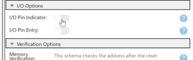
Example: There are three main steps to configuring the I/O pins for the bootloader. Users need to first enable the pins used in bootloader UI, then use the Pin Grid View to select a port number on the device that the I/O pins will use. Lastly, the correct configuration of the chosen pin must be validated.
Configuring I/O Pins
Enable pins from UI
Select a port
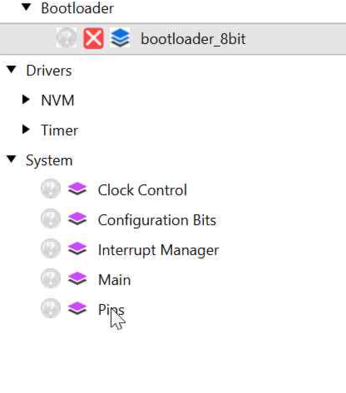
Open Pins UI
Check the pin