7.1 USART with Direct Pin Enable
Direct Mode is a mode in which peripherals are running based on function priority for pins and not using Peripheral Pin Selection (PPS).
Prerequisites
- SDK Setup:
- Getting Started with Software Development (See Getting Started with Software Development from Related Links)
- Software:
- Tera Term
- Hardware:
- PIC32WM-BW1 Curiosity board
Developing Application from Scratch using MCC
- Create a new MCC Harmony Project. For more instructions, refer to Creating a New MCC Harmony Project section from Related Links.
- User can find “Device Resources” window right below the “Project Resource” tab.
- Add SERCOM0 from Peripherals list (Device
Resources>Libraries>Harmony>Peripherals>SERCOM)
Figure 7-2. SERCOM0 Peripheral 
- The following figure illustrates project graph after adding SERCOM0 to the
project resources.
Figure 7-3. Project Graph 
Verify UART Configuration
- Select SERCOM0 component in project graph. SERCOM0 USART provides three
operating modes:
- Ring Buffer mode
- Blocking mode
- Non-blocking mode
Ring Buffer mode:
In Ring Buffer mode, the receiver remains enabled, and the received data is stored in an internal receive ring buffer. The buffer size can be configured using MCC. The application uses API calls to read data from the ring buffer.
APIs are available to query the number of unread bytes available in the receive buffer, free space in the receive buffer and size of the receive buffer.
During transmission, the application data is deep-copied into an internal transmit ring buffer, whose size can also be configured using MCC. This approach allows the use of local buffers for data transmission. APIs are provided to query the available free space, the number of bytes pending transmission, and the total size of the transmit buffer.
Additionally, the application can enable notifications to receive alerts when a specified number of bytes are available in the receive buffer or when a specified amount of free space is available in the transmit buffer. The APIs allow the application to set threshold levels for notifications in both buffers. The application can also enable persistent notifications, which continue until the threshold condition is satisfied.
Figure 7-4. Ring Buffer Mode Configuration Options 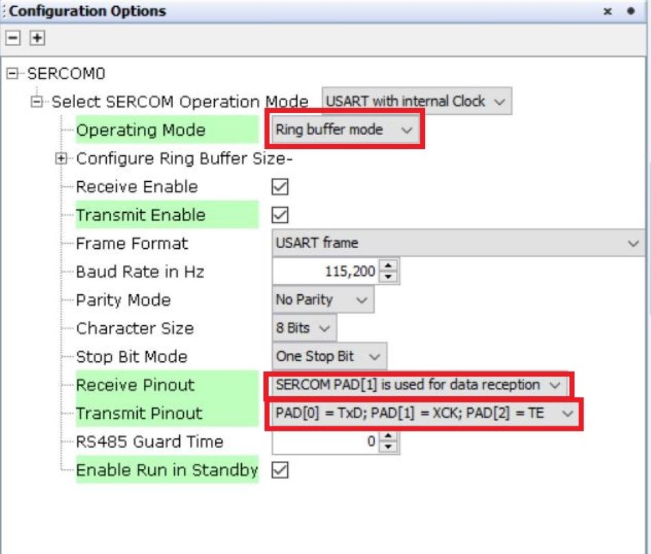
Blocking mode:
In blocking mode, the transfer APIs block until the requested data is transferred.Figure 7-5. Blocking Mode Configuration Options 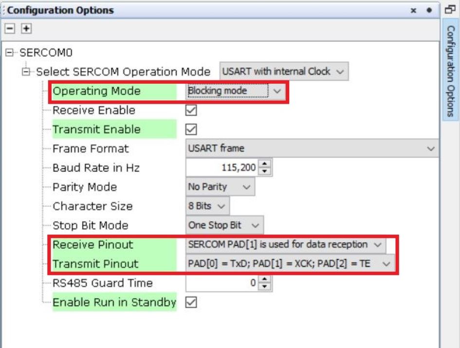
Non-blocking mode:
In non-blocking mode, the peripheral interrupt remains enabled. The transfer API initiates the transfer and returns immediately, while the peripheral interrupt completes the transfer in the background. The application can either register a callback function to receive a notification when the transfer completes or use theIsBusyAPI to check the transfer status.Figure 7-6. Non-blocking Mode Configuration Options 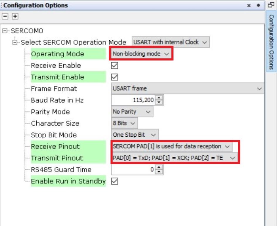
- Select System component in project graph and set SERCOM0 in Direct
mode.
Figure 7-7. System Configuration 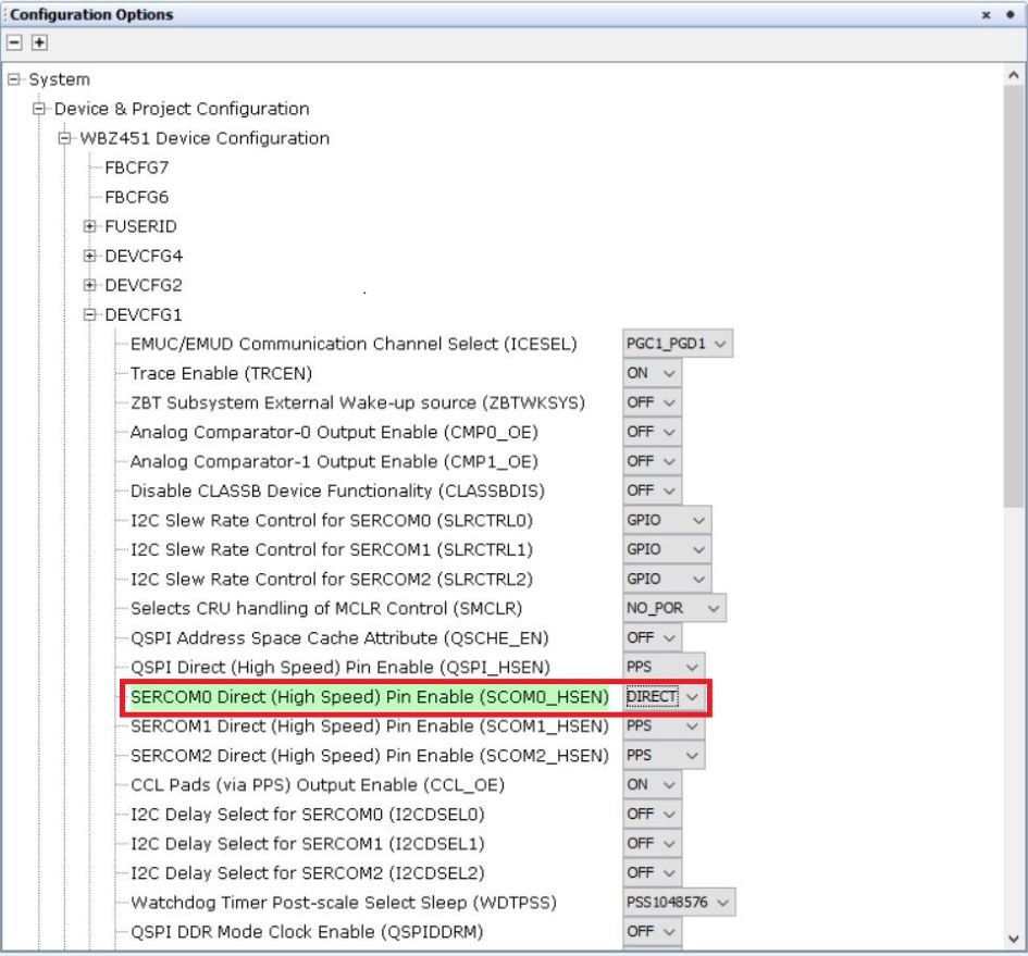
Generating a Code
For instructions on code generation, refer to MPLAB Code Configurator (MCC) Code Generation section from Related Links.
The Sercom initialization routine executed during program initialization can be found in the project files. This initialization routine is automatically generated by the MCC according to the user settings.
Header Files:
- Header File associated with Sercom0 peripheral library or any other peripheral
library for a different example is included in
definitions.hfile.
Function Calls:
- MCC generates and adds the code to initialize the UART peripheral in
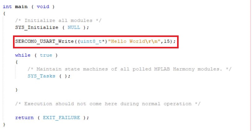
SYS_Initialize()function. SERCOM0_USART_Initialize()is the API that will be called inside theSYS_Initialize()function.- User can exercise
SERCOM0_USART_Write()API to create a “Hello World” application example like this:
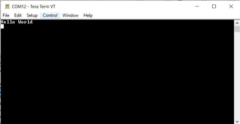
Testing
- Connect the PIC32WM-BW1 Curiosity Board to the PC and
program the application example. Open Tera Term and configure the terminal with
the following settings:
- Speed: 115200
- Data: 8-bit
- Parity: None
- Stop Bits: 1 bit
- Flow Control: None
- Select the COM port that enumerates when the PIC32WM-BW1 Curiosity Board is connected.
- Reset the board to run the application example. The output message appears in Tera Term