
6.1.1 Creating Bootloader from Scratch using MCC
This section outlines the process to configure and generate a standalone bootloader for
the PIC32WM-BW1 device from scratch using MCC. The user
can find the bootloader example code (GPIO trigger) generated using MCC in the wireless_apps_pic32_bw1\apps\bootloader\bootloader_GPIO
path.
The generated bootloader example has the following configurations:
- Enabled UART DFU.
- Enabled console to display messages.
- Enabled GPIO trigger.
- PIC32WM-BW1 Curiosity Board. The DFU mode is triggered by pressing SW2 (GPIO PA2) on the board.
- Automatically reboot firmware after completing the DFU.

The user must follow these steps to create the bootloader example (GPIO trigger) from
scratch.
Note: The recommendation for the new users of MPLAB
Code Configurator is to go through the MPLAB® Code Configurator (MCC) User’s
Guide. For more details, refer to the MPLAB® Code Configurator (MCC)
User’s Guide in the Reference Documentation from Related
Links.
- Create a new MCC Harmony
Project.
- From the “Device”: drop-down list, select PIC32WM_BW1 as target device. For more details on how to create a new MCC Harmony Project, refer to Creating a New MCC Harmony Project from Related Links.
- Launch MCC.
- After launching MCC, in the
Device Resource window, perform the following steps:
- Expand Harmony>Wireless>Driver.
- Click the green (+) symbol next to the “Bootloader” component. This action adds the Bootloader to the Project Graph.
- Click Yes to accept and auto-activate any required dependencies. The MCC automatically adds and connects any additional components needed for the Bootloader to function.
Figure 6-2. Device Resources Window – Bootloader Component 
Figure 6-3. Confirmation for Components Auto-Activation 
- In the Project Graph window,
click Bootloader component to show its configuration options.
Figure 6-4. Bootloader Project Graph Window 
- In the Configuration
Options tab, expand “Bootloader” pane and perform the following
steps:
- Check Enable Bootloader UART DFU.
- From “DFU Mode” drop-down list, select GPIO Trigger.
- From “GPIO Port” drop-down list, select PORT_B.
- From “GPIO Pin”
drop-down list, increase the value to 4.Note: Ensure the PB2 pin is connect to SW2 on the PIC32WM-BW1 Curiosity Board.
- Check Enable Console.
- Leave “ECC Public Key” and “Supported Authentication Methods” at default.
Figure 6-5. Bootloader Options for GPIO Trigger 
- GPIO trigger is the
option to trigger DFU mode, where the user needs to hold the GPIO button
during reset to put the bootloader into DFU mode. Use the “GPIO Port”
and “GPIO Pin” options to change the port and pin based on the user’s
hardware.Note: Other than GPIO trigger, there is also another trigger option, Timer Based Trigger, where the bootloader stays in the DFU mode for a specified amount of time before jumping to the user application. The user can change the DFU Wait Time in Milliseconds to adjust the duration.
- From the “DFU Mode” drop-down list, select Timer Based Trigger. By doing this, the system requests activation of a 32-bit timer component TC0.
- Click Yes to accept adding TC0 and its connection.
The following figures illustrate the timer based trigger
options and the message prompt for adding TC0.
Figure 6-6. Bootloader Options for Timer Based Trigger 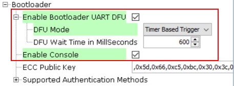
Figure 6-7. Confirmation for Components Auto-activation 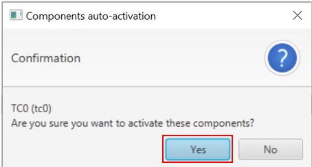
Note: For “Supported Authentication Methods”, there are three methods:- None
- SHA256
- ECDSA256
- In the Configuration
Options tab, expand “Bootloader” pane and perform the following
steps:
- In the project graph window,
select Bootloader component and perform the following steps:
Figure 6-8. SERCOM0 Project Graph Window 
- Right click UART dependency.
- From the “Satisfiers”
list, select SERCOM0 (sercom0). This action adds the SERCOM0
(sercom0) component to the project graph.
Figure 6-9. Dependency of UART 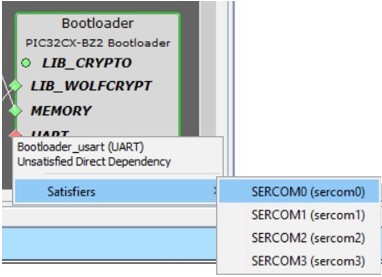
- In the Project Graph window,
click SERCOM0 component to show its configuration options.
- Set the “Receive Pinout” and “Transmit Pinout” options according to the PIC32WM-BW1 Curiosity Board.
- Leave other settings to default.
Figure 6-10. SERCOM0 Options 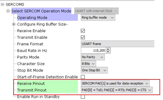
- Expand “Peripherals” tree to add
RCON component.
- Click the green (+) symbol next to the “RCON” component. This action adds the RCON component to the Project Graph.
- Leave RCON options as default.
Figure 6-11. RCON Device Resources Window 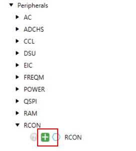
Figure 6-12. RCON Project Graph Window  Note: RCON provides a software reset function. Adding the RCON component enables an automatic firmware reboot after the completion of DFU.
 - Click Generate to create
the bootloader code.
Figure 6-13. Generate Bootloader Code 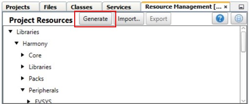
- To ensure the bootloader code
fits within the 24-KB boot memory of the PIC32WM-BW1, perform the following steps:
- Replace
ecc.candcrypt_ecc_pukcl.cwith optimized files fromwireless_pic32cxbz_wbz\utilities\pic32cx-bz\tempBtl.
- Replace
- To enable firmware auto reboot
after the completion of DFU, the host needs to send a new command to bootloader.
This new command is device Reset command, defined to
0x12.- In
progexec.hfile, add the following command:#define DEVICE_RESET_CMD 0x12
Figure 6-14. Code Change in File progexec.h
- Then, in the
progexec.cfile, within theprogram_exec_main()function, add code to handle the device reset (RESET_CMD) command. CallRCON_SoftwareReset()to initiate a software reset. The following figure illustrates the added code.Figure 6-15. Code Change in File progexec.c
Note: After completing the DFU process, the firmware auto-reboot requires a modification on the host side to send the0x12command to reset the device. The Python scripts, which offer an alternative method, have not yet been modified to include this support. - In
- On the MPLAB® X IDE toolbar, click Clean and Build Main Project to
build the code and generate the
bootloader.X.production.hexfile. The precompiled hex files are available atwireless_apps_pic32_bw1\apps\bootloader\bootloader_GPIO\precompiled_hex.Figure 6-16. Build Bootloader Code 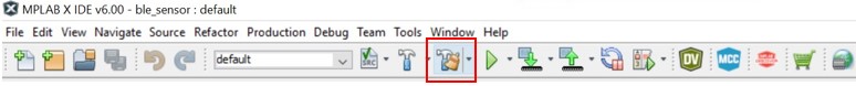
- The user must add the generated bootloader hex file to the user application as a loadable file, but the application does not use it on its own. The following are a few simple steps that the user needs to handle on the application side. For more details, see Configure User Application to Use Bootloader from Related Links.