63.1 MPLAB® Harmony v3 UART-I2C Factory Bootloader for PIC32CZ CA70-MC70
The Bootloader programmed at production by Microchip is an MPLAB Harmony v3-based Bootloader capable of programming an application binary using either the UART or I2C interface.
Key Features:
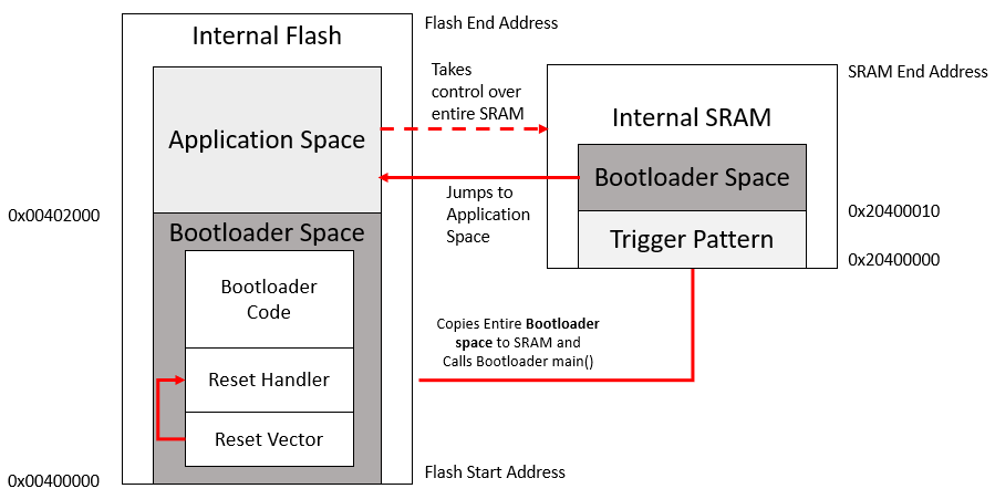
- The Bootloader is programmed at the
Flash memory location (
0x00400000) and takes up to 8KB of Flash memory - The Bootloader startup code copies
the Bootloader from the Flash memory to the SRAM from (
0x20400010) before calling the main function. The main function (and therefore the entire Bootloader) runs from the SRAM to allow upgrading of the Bootloader code itself in Flash memory. - The Bootloader provides a feature to read the current version of the Bootloader by using the read version command
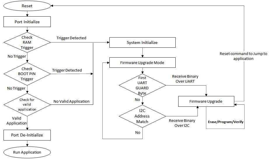
- The Bootloader will provide two ways
to trigger the Bootloader mode:
- External trigger: Bootloader will be triggered based on the status of a dedicated GPIO pin
- Internal trigger: Bootloader will be triggered based on the trigger pattern written at a specific location in the SRAM by the application firmware
- After a new application image is programmed, the Bootloader will verify the programmed application space by generating a CRC-32 value and comparing it with the CRC-32 received from the Host. The application CRC will not be verified after every reset before jumping to the application space for faster startup.
- The Bootloader will read the first
four bytes of application space (
0x00402000) to decide if a valid application is present. If the contents of the first four bytes are not0xFFFFFFFF, then the Bootloader assumes a valid application is present and jumps to the application. If a valid application is not present, then the Bootloader will wait, and remain in Bootloader mode.
Key Requirements:
- By default the Bootloader expects the
application to start from the
0x00402000location. Therefore, the application should be built to start from the0x00402000Flash location. - External Pull-ups must be used for the I2C SDA and SCL lines