7.7.1 Hardware Setup for aWire Programming
Connect aWire using a 6-pin cable between the ISP/PDI connectors.
For routing cards RC36 revision 3, RC38 revision 4, and RC40 revision 2 and older, use the following procedure:
- Mount the routing and socket card and the target device. See the Socket System section on how to do this.
- Connect a cable between Pin3 (TDO) on the JTAG header on the blue area and Pin6 (Reset) on the JTAG header on the green area. See the picture below.
- Ensure that the VTARGET jumper is mounted and that the voltage is within the operating range for the target device.

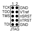
The pinout of the 10-pin JTAG header is shown below: