
7.1.1 Hardware Setup for On-board Programming
- Mount the routing and socket card and the target device. See the Socket System section on how to do this.
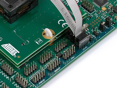
- Connect a 6-wire cable between the two 6-pin ISP headers on the STK600. See the picture below.
- Ensure that the VTARGET jumper is mounted and that the voltage is within the operating range for the target device.
See the Programming Dialog pages in the Microchip Studio help file for information on the STK600 programming dialog.
The pinout of the 6- and 10-pin ISP headers are shown below:
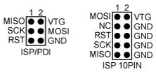
It is not necessary to remove the ISP cable while running a program on the AVR device. The port pins used for ISP programming can be used for other purposes in the user's program.
See also section In-System Programming of an External Target System.