7.5.1 Hardware Setup for On-Board Programming
- Mount the routing and socket card and the target device. See the Socket System section on how to do this.
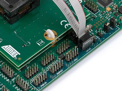
- Connect a 6-wire cable between the two 6-pin ISP/PDI headers on the STK600. See the picture below.
- Ensure that the VTARGET jumper is mounted and that the voltage is within the operating range for the target device.
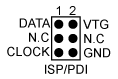
The pinout of the 6-pin ISP/PDI header when in PDI mode is shown below: