
7.2.1 Hardware Setup for On-Board Programming
Follow the steps below to do Parallel High-Voltage Programming. Note that this interface is only intended for use with on-board STK600.
- Mount the routing and socket card and the target device. See the Socket System section on how to do this.
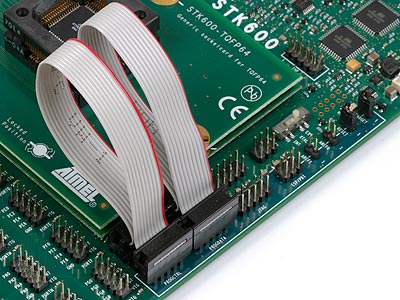
- Use the two 10-wire cables supplied with the STK600 to connect the PROG DATA and the PROG CTRL to the target device, as shown in the picture below.
- Mount both the VTARGET jumper and the RESET jumper.
- Ensure that VTarget is between 4.5V and 5.5V.
See the Programming Dialog pages in the Microchip Studio help file for information on the STK600 programming dialog.
Note: The AREF jumper must be removed before
programming of devices that have AREF on a pin used by the high-voltage programming
interface.
Devices that are affected by this use the following routing cards:
- STK600-RC008T-7
- STK600-RC020T-8
- STK600-RC014T-12
- STK600-RC020T-23