7.8.1 Hardware Setup for On-Board Programming
- Mount the appropriate cards and the target device. See the Socket System section on how to do this.
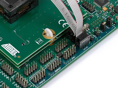
- Connect a 6-wire cable between the two 6-pin ISP/PDI headers on the STK600. See the picture below.
- Ensure that both the VTARGET and RESET jumpers are mounted.
- Set VTARGET to 5.0V (5V is required for programming with TPI).
- Set the clock selection switch to “INT” to disconnect the STK600 programmable clock source from TPICLK.
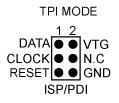
The pinout of the 6-pin ISP/PDI header when in TPI mode is shown below: