3.1 Connecting the Two Boards
(Ask a Question)This section describes how to connect the two boards though the Microchip PCIe Adapter Card.
To connect the boards, perform the following steps:
- Ensure that the pins 1 and 2 of the J1 jumper on the PCIe adapter card are closed.
- Ensure that the pins 1 and 3 of the J2 jumper on the PCIe adapter card are open.
- Connect CON1 of the adapter card to CON3 (PCIe slot) of Board A.
- Connect CON2 of the adapter card to CON3 (PCIe slot) of Board B.
- Connect the USB cable from the Host PC to J5 (FTDI port) on Board A.
- Connect the USB cable from the Host PC to J5 (FTDI port) on Board B.
- Connect the power supply cable to the J3 connector of the PCIe adapter card.
- Power-on Board A and B using the SW3 slide switch.
- Power-up the PCIe adapter card using the SW1 slide switch.
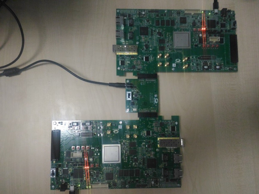
Board A and Board B power-up using the PCIe adapter card. The following figure shows a demo setup after the two boards are successfully connected.