1.5 DWDT Timeout
This example application shows how to generate a Dual Watchdog timer reset by simulating a deadlock.
Description
This example application configures Dual watchdog timer to run in window watchdog mode. Watchdog period is 4 seconds, with 1 second repeat threshold and 3 second level threshold. The switch is used to simulate deadlock and repeat threshold violation. Blinking LED simulates a normal process. When the application is run, the watchdog is cleared after every 2 seconds.
Pressing switch will emulate a deadlock by not clearing the watchdog. LED will remain turned on. 3 seconds after previous watchdog clear, level interrupt will be generated. 4 second after previous watchdog clear, MCU will be reset.
Downloading and Building the Application
To clone or download this application from Github, go to the main page of this repository and then click Clone button to clone this repository or download as zip file. This content can also be downloaded using content manager by following these instructions.
Path of the application within the repository is apps/dwdt/dwdt_timeout/firmware.
To build the application, refer to the following table and open the project using its IDE.
| Project Name | Description |
|---|---|
| pic32cx_mtsh_db.X | MPLABX project for PIC32CXMTSH Development Board |
Setting Up the Hardware
The following table shows the target hardware for the application projects.
| Project Name | Board |
|---|---|
| pic32cx_mtsh_db.X | PIC32CXMTSH Development Board |
Setting Up PIC32CXMTSH Development Board
- Power on the board using a 12V power supply on J3
- Attach a debugger to the SWD/JTAG port J17
Running the Application
- Open the Terminal application (Ex.: Tera term) on the computer
- Connect to the EDBG/JLink Virtual COM port and configure the serial settings as
follows:
- Baud : 115200
- Data : 8 Bits
- Parity : None
- Stop : 1 Bit
- Flow Control : None
- Build and run the application using its IDE
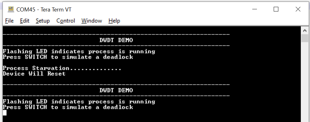
- Console should show the following output and LED should be blinking

- Press Switch to emulate a deadlock
- Console output is updated as follows and LED is turned on:

- LED starts blinking and a reset print on console indicating a MCU resetRefer to the following table for Switch and LED names for different boards:
Board Switch Name LED Name PIC32CXMTSH Development Board Scroll Down Red LED (D20)
