3.4.4.1 GPIO Instrumentation
By inserting simple GPIO toggling in the application code, the user can generate common reference points between the measured current and the code execution. The Data Visualizer is capable of showing the GPIO events in the same graph as the current measurements.
A mass storage application will be used to demonstrate the use of GPIO instrumentation.
Both Target USB and Debug USB connectors of a SAM L21 Xplained Pro board is connected to a host computer. The ATSAML21 target device is running the USB Device MSC Example from ASF for SAM L21 Xplained Pro (in Atmel Studio select File→New→Example Project and search for “MSC”). The Current Measurement jumpers on the kit are set to measure MCU current and bypass I/O current.

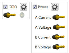
A disk format operation consists of both read and write operations, but with just the current it is difficult to tell what is going on when. To be able to separate the read and write operations, the application code is modified to set GPIO0 (PB01 on the ATSAML21) high on the start of a read operation and set it low at the end of the read operation. GPIO1 (PA16 on the ATSAML21) is similarly toggled for write operations. Both the GPIO interface and the Power interface must be enabled in the DGI Control Panel of the Data Visualizer as shown below.

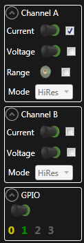
In the Control Panel of the Power Analysis module disable GPIO2 and GPIO3 as shown below.

With the GPIO signals enabled, the user can distinguish the current consumption of the read and write operations. The yellow signal is GPIO0 which signals the read operations and the green signal is GPIO1 showing the write operations.

