5 Programming the PolarFire Device and SPI Flash
(Ask a Question)This section describes how to program the PolarFire device and SPI Flash.
To program the PolarFire device, perform the following steps:
- Ensure that the jumpers on the
evaluation board are set as specified in the following table.
Table 5-1. Jumper Settings—Evaluation Board Jumper Description J18, J19, J20, J21, and J22 Close pin 2 and 3 for programming the PolarFire FPGA through FTDI J28 Close pin 1 and 2 for programming through the on-board FlashPro5 J26 Close pin 1 and 2 for programming through the FTDI SPI J27 Close pin 1 and 2 for programming through the FTDI SPI J23 Open pin 1 and 2 for programming SPI Flash J4 Close pin 1 and 2 for manual power switching using SW3 J12 Close pin 3 and 4 for 2.5 V - Connect the power supply cable to the J9 connector on the evaluation board.
- Connect the USB cable from the host PC to J5 (FTDI port) on the evaluation board.
- Power on the evaluation board using the SW3 slide switch.
The following figure shows the PolarFire Evaluation Kit set up to be programmed.
Figure 5-1. Board Setup-Evaluation 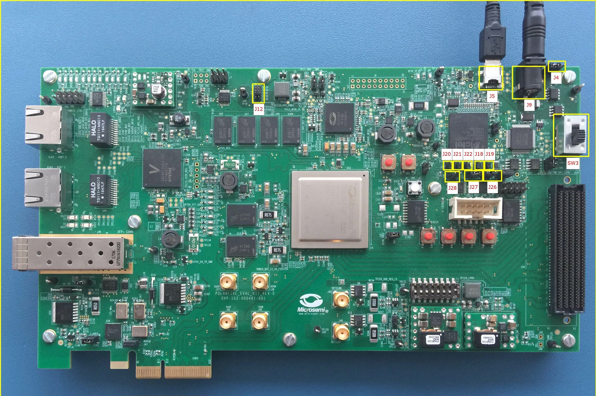
- Refer Appendix 4: Running the TCL Script to create Libero Project and open the project.
- Click Run PROGRAM Action to program the device.
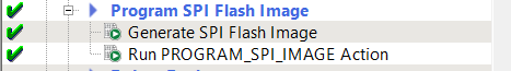
- Double click Run
Program_SPI_IMAGE Action to program the SPI flash. A green tick mark is
displayed after the successful generation, see the following figure.
Figure 5-2. Program SPI Flash Image